
3.3.8 Emission, reference, VLR bandwidth relationship and bandwidth correction factor
The proposed exercise considers the case where the VLR bandwidth is the same as the emission bandwidth and the reference bandwidth.
This section aims at illustrating the interaction between the emission bandwidth (ItBW), reference bandwidth (Bref), VLR bandwidth (VLRBW) and any bandwidth correction factor. This section provides examples where these values are different and its’ effect on the iRSS calculation.
Relationship between Emission bandwidth and Reference bandwidth
For a fixed VLRBW = 200 kHz, and fixed ItBW= 200 kHz, the attenuation Att(dBc/Bref) will be different depending on the values of the Bref in order to achieve the same interference power level.
Case 1, ItBW > Bref :
Bref = 100 kHz, with Att = -3 dBc/Bref, iRSS = -54.49 dBm;
As mentioned in Section A7.5 on p.287, if the reference bandwidth is lower than the emission bandwidth then the attenuation must be defined with negative sign;
Case 2, ItBW = Bref:
Bref = 200 kHz, with Att = 0 dBc/Bref, iRSS = -54.49 dBm;
If the reference bandwidth is equal to the emission bandwidth then the attenuation should be set as zero.
Case 3, ItBW < Bref:
Bref = 400 kHz, with Att = 3 dBc/Bref, iRSS = -54.49 dBm;
If the reference bandwidth is larger than the emission bandwidth then the attenuation must be defined with positive sign.
Please note that, it is best practice and recommended that the user set the reference bandwidth as the same value as the bandwidth of the emission mask, to avoid any unexpected scaling effect.
Relationship between Emission bandwidth and Victim link receiver bandwidth
For a fixed Bref = 200 kHz and a fixed ItBW= 200 kHz, depending on the size of the VLRBW a bandwidth correction factor is applied or not. Calculations presented here are mainly illustration of effect or relation between emission Bw nad VLR Bw in the co-frequency case.
Case 4, ItBW = VLRBW:
VLRBW = 200 kHz, iRSS = -54.49 dBm;
Case 5, ItBW > VLRBW:
VLRBW = 100 kHz, iRSS = -57.5 dBm;
As shown in ANNEX 22: on p. 422, when the ItBW > VLRBW, the interfering power in the VLR is reduced due a bandwidth correction factor automatically applied in SEAMCAT. As a results, the iRSS value decreases compare to a case where ItBW = VLRBW.
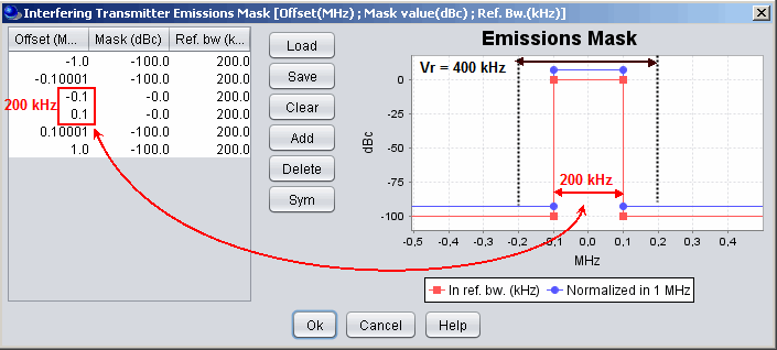
Case 6, ItBW < VLRBW: Case of ILT Spectrum emission mask when the Tx spectrum is sharply reduced outside its reference bandwidth
VLRBW = 400 kHz, iRSS = -54.49 dBm;
As illustrated in ANNEX 22:, when the ItBW < VLRBW, there is no bandwidth correction factor applied to the interfering emitted power since the all the energy is “seen” by the VLR. Therefore the iRSS is equal to the case where ItBW = VLRBW. Note also that since the emission bandwidth of the interferer is smaller than the victim, SEAMCAT will complain that the spectrum emission mask of the interferer is not defined with the range of the victim bandwidth, therefore you need to increase the out of band emission.
Case 7: ItBW < VLRBW: Case of ILT Spectrum emission mask when the Tx spectrum have sloped characteristics outside its reference bandwidth
This is the same as case 6 (VLR = 400 kHz and Bref = 200 kHz) except that the spectrum emission mask (emission bandwidth 200 kHz) has slopes on both sides (Figure 93) which generates higher interference compared to the case 6 and the iRSS = -53.44 dBm
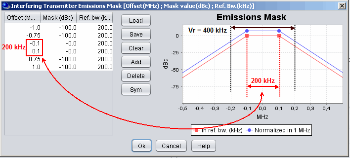
the slope in the emission mask