
3.2.5 Positioning the VLT vs VLR
Define now the positions of transmitters and receivers of the victim link.

Figure 76: Selecting the Tx to Rx path tab
SEAMCAT allows defining the locations of the Victim link receiver and the Victim link transmitter in a fixed manner (correlated) or following some distribution (uncorrelated) as summarised in Figure 77. The input parameters are detailed in section 5.4, and the algorithms are detailed in ANNEX 13:
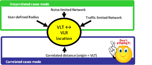
Figure 77: Summary of the VLT ↔ VLR location capability in SEAMCAT
In this exercise, set the distance between the VLT and the VLR as fixed (correlated distance) (x = y = 2 km) as illustrated in Figure 78.
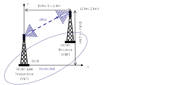
Figure 78: Distance between the Victim link transmitter and the Victim link receiver (Victim Link)
It is assumed that the Tx and Rx are both outdoor as shown in Figure 79.
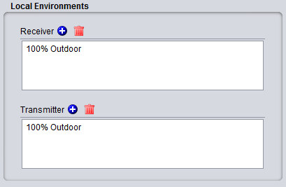
Figure 79: Example of setting up the outdoor/indoor ratio
For this, select the correlated distance option of SEAMCAT as shown in Figure 80. In SEAMCAT, the origin of the coverage radius (see ANNEX 13:) is the transmitter (this is also reminded in the GUI) of the link.

Figure 80: Illustration of the correlated distance in SEAMCAT