
12.1.3 Generic system outline
During the event generation all involved transceivers (ILT, ILR, VLR and VLT) are plotted in graphical display window placed on the simulation outline tab.
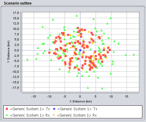
Figure 243: Example of “Scenario outline” for a generic system 1 vs generic system 2 type of simulation
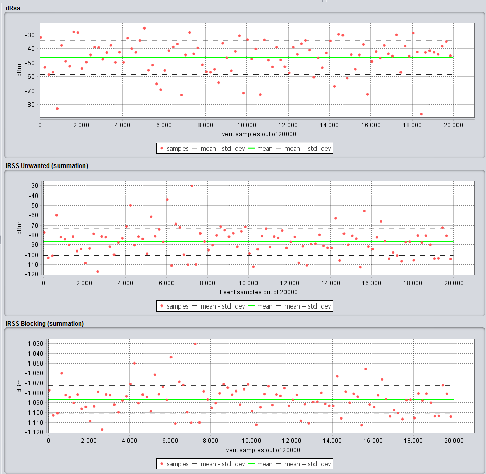
Figure 244: dRSS, IRSS samples
The dRSS and the iRSS vectors are shown for 100 events maximum to avoid overloading the memory and to speed the computation time. The iRSS is shown as a summation of all the interferers.