10.2.2 Auto-generation of multiple interfering links
This option corresponds to duplicate n times a specific interfering links on a circle or on a hexagonal grid as illustrated below in (a) and (b) respectively. It is available by clicking on (  ). These interferers have the same characteristics as the reference interfering link. It has the purpose of automatically generating a regular pattern of interfering links.
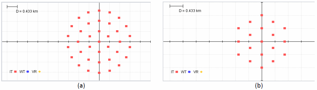
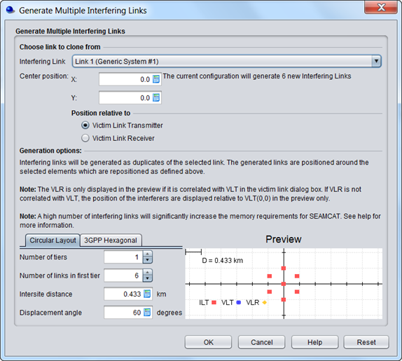
Figure 214: Auto-generation of multiple interfering links
The multiple generate feature graphical interface consists of 3 parts:
-
Selection of the reference interferer
-
Relative position of this reference interferer to the victim link
-
Layout preview of the new interferers
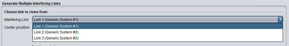
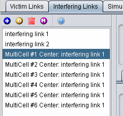
(a) Selection of the reference interferer
You can choose an interfering link that will be used to clone the new interferers.
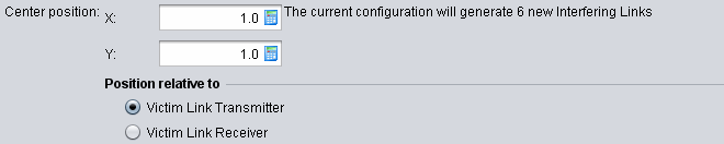
(b) Relative position of this reference interfere to the victim link
You can adjust the position of the interferers with respect to either the VLT (Victim link transmitter) or the VLR (Victim link receiver). When the generate multiple feature is run the relative positioning of interfering link mode (i.e. in the victim receiver to interfering transmitter path tab) is by default overwritten. In this case the center of the interferers is set to (1,1) to VLT.
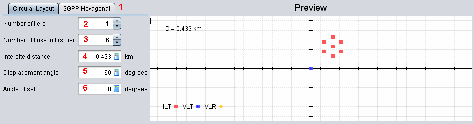
(c) Layout preview of the new interferes
As a results the preview will display the following illustration
In the appearing dialog window, you may select the parameters described in .
Table 41: Generate Multiple Interfering Link GUI input parameters
|
Description |
Symbol |
Type |
Unit |
Comments |
|
Circular or hexagonal layout |
- |
- |
- |
General circular or hexagonal layout |
|
Number of tiers of generated multiple cells |
- |
Scalar |
- |
You can generate as many tiers as you want |
|
Number of links in the first tier |
- |
Scalar |
- |
You can set the total number of links in the first tier |
|
Intersite distance |
D |
Scalar |
Km |
Distance between 2 BSs |
|
Displacement angle |
θ |
Scalar |
Degree |
Angle between the horizontal and the first BS (counter clockwise) |
|
Angle offset |
|
Scalar |
Degree |
Angle offset of the displacement angle |
(d) Illustrative example of the generation of multiple interfering link
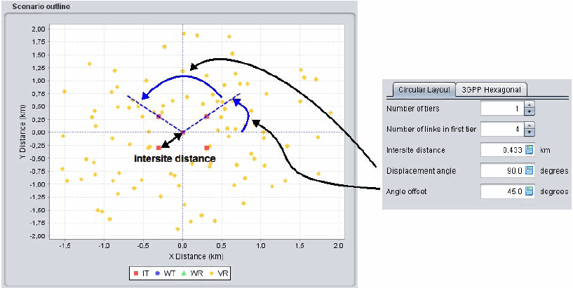
The below figure shows an example of scenario that may be used for estimating intra‐service interference to a victim base station of cellular system from mobile transmitters operating in the next tier of co‐channel cells of the same system.
The displacement angle is calculated automatically by the dialogue window by evenly spacing the specified number of cells around the 360 deg arc, but you may amend this angle. e.g. in order to achieve placement of multiple cells in a sector of less than 360 deg. The parameter angle offset may be used to specify the offset of an azimuth towards the first interfering cell with regard to the x‐axis, as seen from the centre cell.
During the multiple link generation, the intersite distance parameter (0.433 km in the example), in combination with the specified initial offset angle, will overwrite the original coordinates (Delta X/DeltaY) in the Vr‐It path tab setting of the Interfering links.