
5.4.2 Coverage radius
A coverage radius is calculated for both the victim link and the interfering link. It is the 
for the victim link (VLR-VLT) and the  for the interfering link (ILR-ILT) (see Annex A13.1). The receivers will be randomly deployed within the area centred on the transmitter and delimited by the coverage radius if the non-correlated option is selected.
Three different modes are available for calculating the maximum radius .
-
User-defined radius allows directly entering the maximum radius (See Annex A13.1.1);
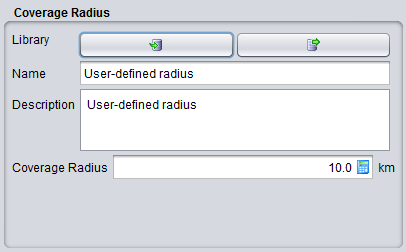
Figure 151: User-defined coverage radius dialog box
Table 16: Description on User-defined coverage radius
|
Description |
Symbol |
Type |
Unit |
Comments |
|
Coverage radius |
Rmax |
Scalar |
km |
The coverage radius defines the coverage of the system, i.e. the maximum distance between an ILT and a ILR or between a VLT and a VLR.
|
- The noise-limited network option will calculate the coverage radius based on the formula for noise-limited network. If this option is chosen, a set of input boxes will appear below allowing the user to enter specific parameters required for this calculation. In this case it is considered that the coverage of the transmitter is limited only by propagation losses and other elements in thelink budget, with received signal operating at the sensitivity limit. The details of the calculation are given in Annex A13.1.2.
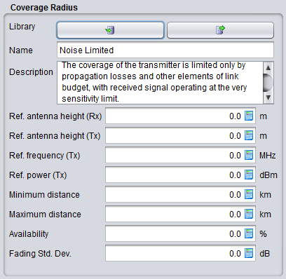
Figure 152: Noise limited network coverage radius dialog box
The coverage radius in the noise-limited network is defined by the parameters of Table 17. Note that the input parameters for the Noise-limited network interface are set to zero by default in order to independently define the radius from some parameters set elsewhere in the link.
|
Description |
Symbol |
Type |
Unit |
Comments |
|
Reference antenna height (receiver): |
h0 |
Scalar |
m |
The height used for coverage radius calculations. If a distribution is used to define the real height, the coverage radius would be different in each trial, here the value may be fixed. |
|
Reference antenna height (transmitter): |
h0 |
Scalar |
m |
The height used for coverage radius calculations. |
|
Reference frequency |
fVLR |
Scalar |
MHz |
|
|
Reference power |
PVLT |
Scalar |
dBm |
|
|
Minimum distance |
|
|
km |
|
|
Maximum distance |
|
|
km |
|
|
Availability |
|
|
% |
|
|
Fading standard deviation |
|
|
dB |
|
|
Reference percentage of time |
|
|
% |
|
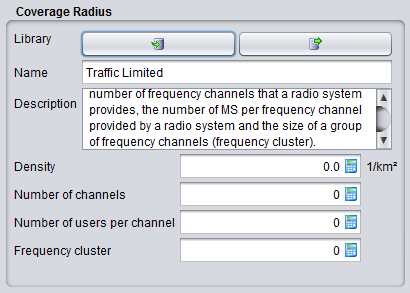
Traffic-limited network option will calculate the coverage radius, based on the formula for traffic-limited network. If this option is chosen, a set of input boxes will appear below allowing user to enter specific parameters required for this calculation (See Annex A13.1.3).
The consistency of this parameter should be verified against the sensitivity, so that if a receiver is placed at given distance (e.g. at the maximum coverage radius) the received power is higher than the sensitivity for a reasonable percentage of occurrences (availability).