
4.8 Protection distance
If a minimum protection distance between the victim link receiver and interfering link transmitter is introduced then the simulation radius may then be calculated by using the following formula:
 (Eq. 30)
Note: The calculation of the iRSS at each trial will be performed only if the location of the ILT satisfies the following condition

.
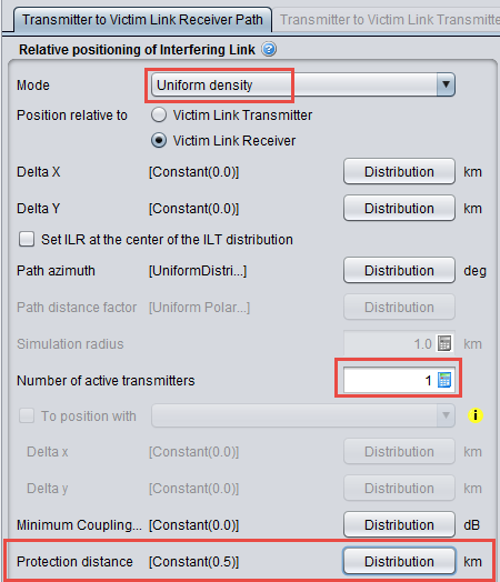
Figure 129 presents how to set-up SEAMCAT (See also A13.2 for further details).
The simulation radius (see Figure 131) may then be calculated by using the following formula:

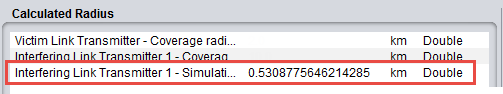
If the distance between the VLR and the ILT is equal to the protection distance (0.5 km), then:

If the distance between the VLR and the ILT is equal to the simulation radius (0.531 km), then:

These results are in line with those depicted on Figure 131. We can then increase the number of active transmitters to 10 as shown in Figure 132.
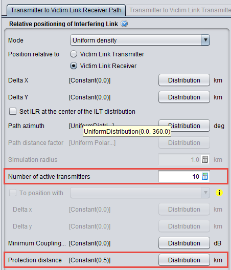
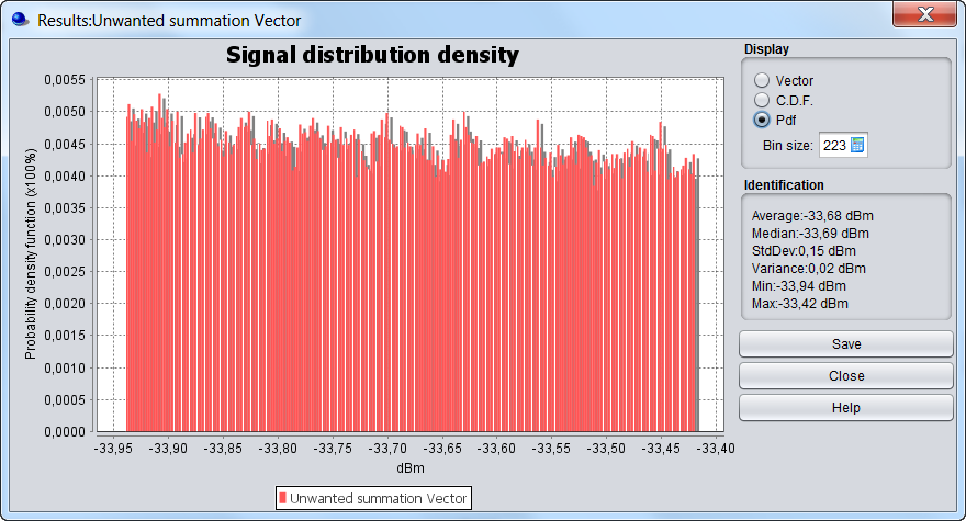
The simulation radius may then be calculated by using the following formula (see Figure 133 for the result):

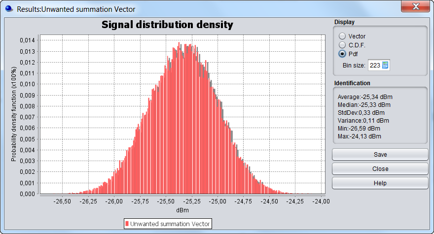 Figure 133: Calculation of the Rsimu and the iRSSunwanted using the protection distance
(for 10 active interferer)
If the distance between the VLR and a single ILT is equal to the protection distance, then:

If the distance between the VLR and a single ILT is equal to the simulation radius, then:

If 10 transmitters are deployed around the VLR then:
 and
and

 (see Figure 133)