Beamforming Subarray Active Antenna Systems
Active Antenna System
Active Antenna System are described in Recommendation ITU-R M.2101 and the extended sub-array AAS model with suggested parameters in ITU-R Working Party 5D Chairman's Report in Chapter 4 Annex 4.4 ITU-R WP5D document 5D/716 "Characteristics of terrestrial component of IMT for sharing and compatibility studies in preparation for WRC-23" or 3GPP TR 38.803 Section 5.2.3.2.4. The background information for the AAS model can be found in ITU-R WP5D document 5D/701-E.
Sub-array AAS plugin parameters
For the sub-array AAS plugin the following parameters can be set:
-
Azimuth additional offset, see A11.3
-
Elevation additional offset, see A11.4. The mechanical downtilt depends on the deployment scenario, see in ITU-R WP5D document 5D/716 or 3GPP TR 38.803 Section 5.2.3.2.4.
-
Number of elements in horizontal direction, number of subarrays in vertical direction and number of elements per sub-array in vertical direction (positive integers), see example figure below. The figure is from ITU-R WP5D document 5D/701-E showing AAS panel with 8 columns (number of elements in horizontal direction), 4 rows (number of subarrays in vertical direction) and of 3x1 sub-arrays (logical elements).
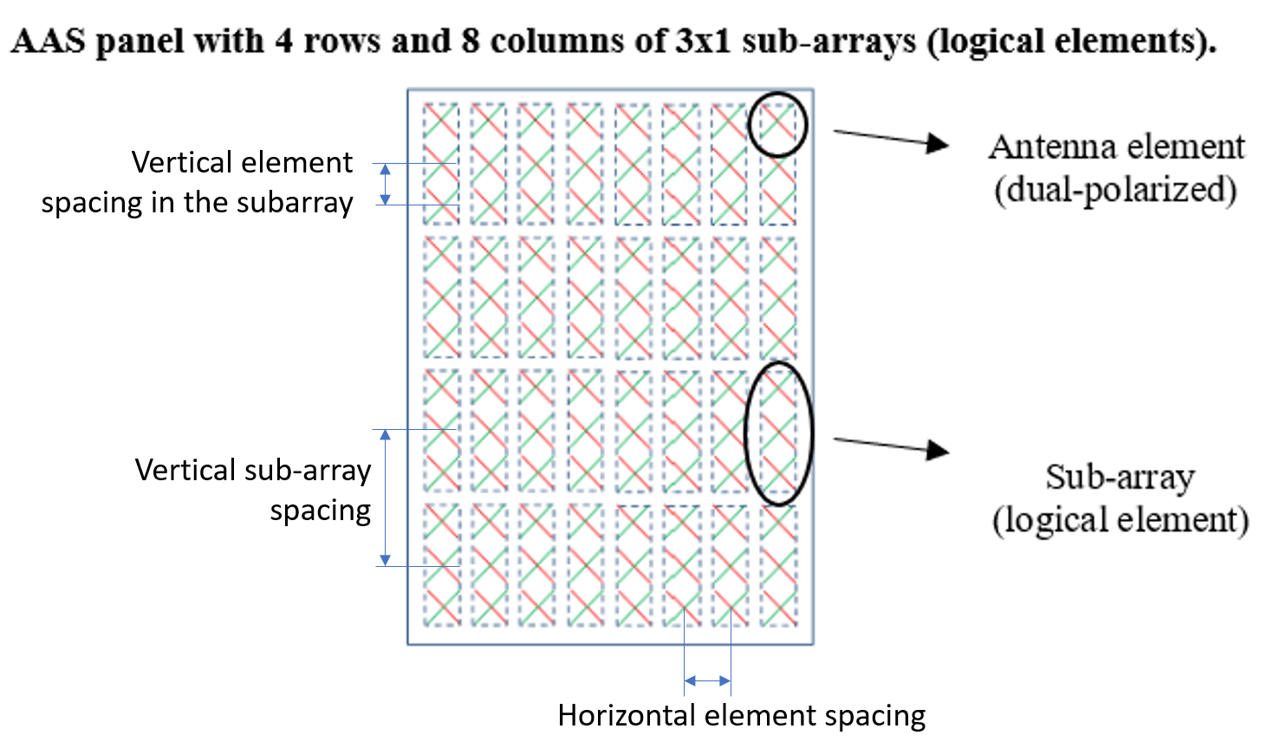
The horizontal element spacing, vertical sub-array spacing (centre-to-centre) and vertical element spacing in the subarray (positive real numbers) are expressed relative to the wavelength (dh,v/). The "vertical sub-array spacing" has to be greater than or equal to the default value corresponding to the product of the "vertical element spacing in the subarray" and the "number of elements per sub-array in the vertical direction".
-
Pre-set sub-array downtilt is an electrical fixed downtilt in the sub-array. The pre-set sub-array downtilt depends on the deployment scenario, see in ITU-R WP5D document 5D/716 or 3GPP TR 38.803 Section 5.2.3.2.4.
-
Limit coverage range selected will enable the selection for:
-
Minimum and maximum vertical coverage range limit for the beamforming. Typical value for macro coverage scenarios are in the range from 0 to -10 degrees and for micro coverage from 0 to -30 degrees (see in ITU-R WP5D document 5D/716 or 3GPP TR 38.803 Section 5.2.3.2.4). They are expressed in SEAMCAT coordinate system with the horizontal plane fixed at zero degree elevation. This setting is independent of the set mechanical antenna tilt. The minimum value must be smaller than the maximum value.
-
Minimum and maximum horizontal coverage range is typically ±60 degrees from the antenna boresight for a three-sector base station site.
-
Minimise system link gain outside coverage range. If selected this will effectively set the coupling loss to the UEs that are not within the vertical coverage range to infinite. If not selected, the gain to these UEs will be the resulting gain of the antenna gain envelope with the maximum gain limited to the maximum coverage range.
-
-
For Element antenna setting, see below.
-
Adjacent channel simulation "use composite antenna pattern" for fully correlated beamforming within the band and adjacent band and "sub-array antenna pattern" for adjacent bands. See TR 37.840 on correlated and uncorrelated beamforming. Beamforming will be less correlated if frequency separation between wanted signal (interferer) and victim increases.
The pre-set typical values in the antenna plugin are for suburban macro case in 1 710-4 990 MHz frequency range. For other configurations see ITU-R Working Party 5D Chairman's Report in Chapter 4 Annex 4.4.
Single-element AAS setting without multiple elements in sub-array
For single-element AAS without multiple elements in a sub-array (e.g. for micro cell with 8x8 elements) the following parameters can be used (see in ITU-R WP5D document 5D/716, Table 9):
-
Number of elements in horizontal direction: 8
-
Number of subarrays in vertical direction: 8
-
Horizontal element spacing: 0.5
Same settings as used in "BeamFormingComposite" antenna plugin for AAS with 8x8 elements. For the sub-array the following values need to be set
-
Number of elements per sub-array in vertical direction: 1
-
Vertical element spacing in the subarray: 0.7
-
Pre-set sub-array downtilt = 0
The elevation additional offset with e.g. -10 degrees.
Beamforming element antenna parameters for sub-array AAS
For the Beamforming Element Antenna the following parameters can be set
-
Antenna peak gain with typical value is 6.4 dBi includes the array ohmic loss of 2 dB and some normalisation of the antenna gain over the sphere. The element antenna gain is per polarisation
-
Azimuth 3dB beamwidth typical value with 90 degrees for sub-array AAS
-
Vertical 3dB beamwidth typical value with 65 degrees for sub-array AAS
-
Front to back ratio and side-lobe level limit can be set to e.g. 30 dB to consider practical limits



SEAMCAT equations for limiting sub-array coverage range
φ: Azimuth angle (0 to 360°)
θ: Elevation angle (-90 to 90°, negative = down)
A: origin point (ILT,ILR,VLT,VLR)
B: target point (ILT,ILR,VLT,VLR)
φhA→B: Antenna azimuth from A to B in horizontal plane
θhA→B: Antenna elevation from A to B with respect to in horizontal plane
φA→B: Transformed antenna azimuth from A to B in the plane perpendicular to boresight
θA→B: Transformed antenna elevation from A to B with respect to boresight
θhcov,min: Minimum vertical coverage range with respect to horizontal plane
θhcov,max: Maximum vertical coverage range with respect to horizontal plane
φhcov,min: Minimum horizontal coverage range in horizontal plane
φhcov,max: Maximum horizontal coverage range in horizontal plane
θcov,min: Minimum vertical coverage range with respect to boresight
θcov,max: Maximum vertical coverage range with respect to boresight
φcov,min: Minimum horizontal coverage range in the plane perpendicular to boresight
φcov,max: Maximum horizontal coverage range in the plane perpendicular to boresight
β: mechanical downtilt (positive = down)
θi,etilt: elevation beam steering angle with respect to mechanical boresight (positive=down)
φi,escan: azimuth beam steering angle in the plane perpendicular to mechanical boresight
Angle transformations:




The beam steering angles are limited to the minimum and maximum coverage angles as follows:

Alternatively:


Alternatively:

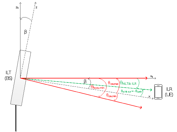
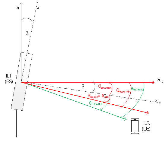
Figure 2: Elevation example of ILT→ILR link with ILR (UE) outside vertical coverage range (θILT→ILR<θcov,min)
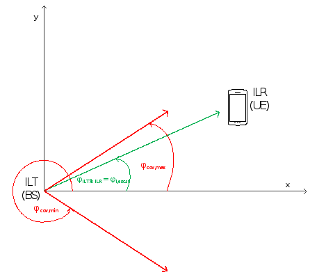
Figure 3: Azimuth example of ILT→ILR link with ILR (UE) within horizontal coverage range (0≤φILT→ILR<φcov,max)
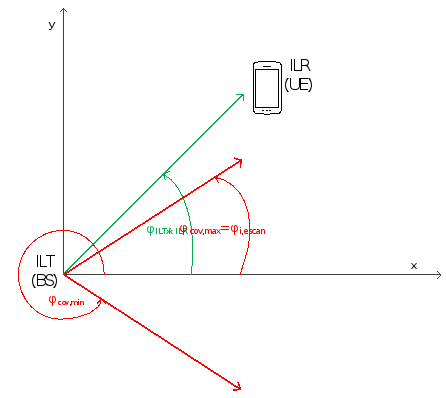
Figure 4: Azimuth example of ILT→ILR link with ILR (UE) outside horizontal coverage range (φcov,max≤φILT→ILR<180)