# 9a IMT-2020 MODULE
# INTRODUCTION
'IMT-2020', better known as 5G, is implemented in SEAMCAT according to the specifications outlined in Recommendation ITU-R M.2101 – 'Modelling and simulation of IMT networks and systems for use in sharing and compatibility studies' \\\[ref\\\].
The SEAMCAT implementation and user interface for IMT-2020 systems is similar to the OFDMA module. The main differences are the inclusion of different system types (as outlined in 10.2 below) and the use of beamforming array antennas, also known as active antenna systems (as outlined in 10.6 below). Unless specified otherwise in the following sections, the features are implemented in the same manner as for OFDMA systems according to section [9](https://ecowiki.atlassian.net/wiki/spaces/SH/pages/512134/9+OFDMA+module#id-9OFDMAmodule-9 "https://ecowiki.atlassian.net/wiki/spaces/SH/pages/512134/9+OFDMA+module#id-9OFDMAmodule-9").
# IMT-2020 SYSTEM TYPES
There are two different types of network structure: Homogeneous networks and Heterogeneous networks. A homogeneous network structure consists of a single base station type. It can be a macro, a micro or an indoor base station. A heterogeneous network structure consists of combination of at least two base station types. For a large area or nationwide studies, a combination of network structures may be required.
In designing IMT-2020 systems for SEAMCAT scenario, user can consider three different types of network structure: Macro system, Micro system and Hybrid system as shown below. There are number of predefined systems and user can define his own system to be used in SEAMCAT study if none of the predefined systems are not appropriate.
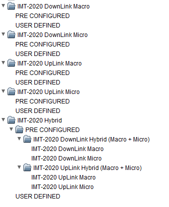
Figure: Overview of IMT-2020 system types preconfigured in SEMCAT Systems library
## Macro system
Macro system represents cellular system using macro base stations used for seamless wide area coverage. Macro base stations are often deployed above roof-top. Cell sizes in IMT networks can vary considerably depending on the deployment (urban, suburban, rural), environment, carrier frequency and the base station's type. In Macro system in SEAMCAT user can select system for simulation as either UpLink or DownLink.
## Micro system
Micro system is an element system which consists of micro cell cluster which can be considered as standalone system or can be fitted within macro system configuration. In the urban environment, micro base stations are generally deployed below roof-top. DL/UL
## Hybrid system
Hybrid system in SEAMCAT is composed of macro cells and microcells. Micro cell clusters are distributed in a macro cell coverage area. Each cluster consists of two cells which are positioned randomly in macro cell sector. For hybrid system to be feasible cell radius of macro system have to be enough to fit IMT-2020 micro cells. There are two predefined IMT-2020 hybrid systems IMT-2020 DownLink Hybrid Macro + micro and IMT-2020 UpLink Hybrid Macro + micro. For Hybrid systems SEAMCAT shows characteristics of Aggregate system and System layout. To see or edit characteristics of subsystem user need to expand tree node and chose individual system as shown below.
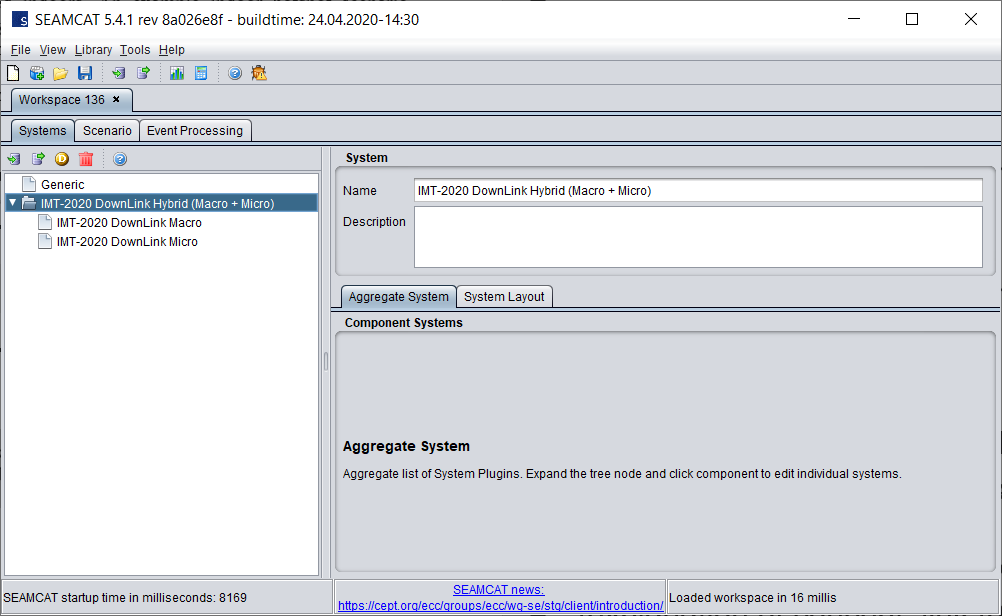Figure: Overview of the IMT-2020 hybrid system in SEAMCAT showing individual subsystems
# IMT-2020 TX AND RX SETTINGS
IMT-2020 system tab has similar interface as OFDMA system as explained in section [9.3.](https://ecowiki.atlassian.net/wiki/spaces/SH/pages/512115 "https://ecowiki.atlassian.net/wiki/spaces/SH/pages/512115")
# ALGORITHM DESCRIPTION
The simulation algorithm is implemented according to the specification outlined in Rec. ITU-R M.2101 – section 3.4.1 for downlink and section 3.4.2 for uplink. This implementation addresses both cases of IMT-2020 as the interfering and victim system.
Flowcharts describing the specific SEAMCAT implementation are provided in [Annex 15](https://ecowiki.atlassian.net/wiki/spaces/SH/pages/494646 "https://ecowiki.atlassian.net/wiki/spaces/SH/pages/494646").
Note that the number of UEs per BS *K* is not set explicitly in SEAMCAT but is derived from the user parameters 'Max. RBs per BS' (parameter *M* in M.2101) and 'Number of RBs per MS' (parameter *n* in M.2101), i.e.:
[](https://wiki.cept.org/uploads/images/gallery/2026-04/SWFjuqJYf11DEKNS-image.png)
The *K* users are distributed randomly within the sector of each BS.
Power control is implemented similarly to OFDMA systems (see section [9.10](https://ecowiki.atlassian.net/wiki/spaces/SH/pages/493458 "https://ecowiki.atlassian.net/wiki/spaces/SH/pages/493458")), as recommended in M.2101 section 4.1.
# BEAMFORMING ANTENNAS IN IMT-2020 SYSTEMS
# Introduction
A key. feature of IMT-2020 systems are beamforming array antennas which use phase shifting to an array of individually fed antenna elements to dynamically steer a beam towards a specific user in order to maximise throughput.
The main beamforming antenna as specified in SEAMCAT is the Beamforming (Composite) antenna, which is in-line with the specifications outlined in section 5 of Rec. ITU-R M.2101. An implementation of 3GPP TR 37.840 is also available – the differences between these implementations are explained below.
Beamforming antenna arrays in SEAMCAT are specified at two levels – first the individual element antenna is specified as a regular antenna plugin, which is then used to form the larger array specified in a separate plugin. These are described in the following sections
# Beamforming element antenna
The beamforming element antenna is specified as a standard equation based antenna plugin in SEAMCAT.
[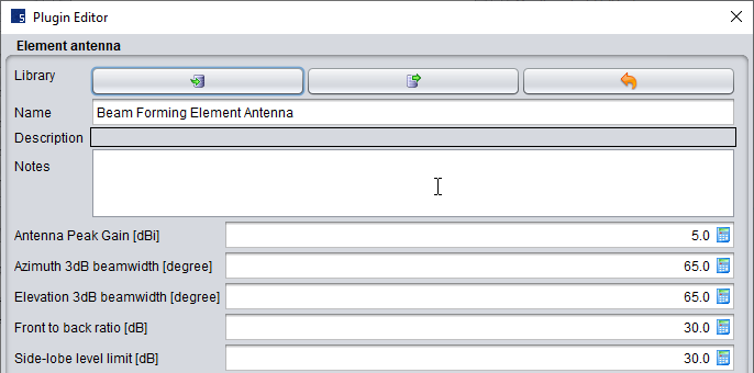](https://wiki.cept.org/uploads/images/gallery/2026-04/X3zoF30ZmKCUTfdj-image.png)Figure: Beamforming element antenna parameters
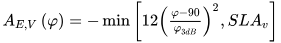
The input parameters and the corresponding notation as used in the following equations are:
- Antenna Peak Gain (dBi): GE,max
- Azimuth 3dB beamwidth (degrees): θ3dB
- Elevation 3dB beamwidth (degrees): φ3dB
- Front to back ratio (dB): Am
- Side-lobe level limit (dB): SLAv
The total gain AEθ,φ is calculated as follows:
[](https://wiki.cept.org/uploads/images/gallery/2026-04/V3slVAjJp5HLZ6oS-image.png)
[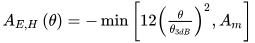](https://wiki.cept.org/uploads/images/gallery/2026-04/3euL5HLM3RoaYlN6-image.png)
[](https://wiki.cept.org/uploads/images/gallery/2026-04/WjRA3Azf6dKYNRdE-image.png)
Note that the notation for azimuth and elevation planes in these sections is the opposite of that used in M.2101 – this is for consistency with the wider SEAMCAT conventions, where φ=elevation and θ=azimuth.
This implementation is equivalent to the 3GPP TR 36.814 antenna pattern (Table A.2.1.1-2) which is also available in SEAMCAT as a separate antenna.
Note that it is possible to use the element antenna in isolation (i.e. not as part of a beamforming array), however in this case any tilt settings will not be handled correctly. For this case it is recommended to instead use the 3GPP TR 36.814 antenna plugin directly.
# Beamforming composite antenna
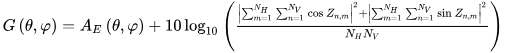
Once the element antenna has been specified, it can be applied to the composite array plugin which specifies the dimensions of the array:
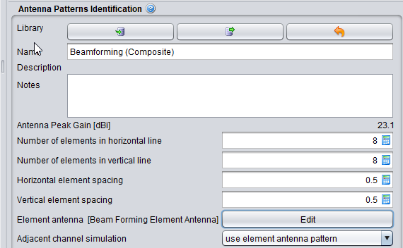
Figure : Beamforming composite array parameters
The element antenna can be modified by selecting Edit next to Element antenna. The other input parameters and the corresponding notation as used in the following equations are as follows
- Number of elements in horizontal line: NH
- Number of elements in vertical line: NV
- Horizontal element spacing (relative to the wavelength of the wanted signal): dHλ
- Vertical element spacing (relative to the wavelength of the wanted signal): dVλ
The parameter "Adjacent channel simulation" determines how beamforming is handled in adjacent channels, with the following options:
1. "use element antenna pattern": in this case **no beamforming** **is applied** outside of the system link's own channel. This is in line with the M.2101 specifications
2. "use composite antenna pattern": in this case **beamforming is applied** outside of the system link's own channel. This option provides additional flexibility to the user, recognising that in practice some degree of beamforming will occur in nearby channels (see section 10.6.4 below for additional options).
For example:
- If VLR uses Beamforming antenna and is selected "use element antenna pattern" then for Unwanted interference SEAMCAT will use composite antenna gain for VLR and for Blocking interference it will use element antenna gain for VLR (outside channel).
- If ILT uses Beamforming antenna and is selected "use element antenna pattern" then for Unwanted interference SEAMCAT will use element antenna gain for ILT (outside channel) and for Blocking interference it will use composite antenna gain for ILT.
The antenna peak gain is pre-calculated and shown for the input parameters (e.g. 23.1 dBi in Figure above). This is provided for validation purposes.
Tilting of antennas is handled as for other antennas (see section x.y.z).
The beamforming gain Gθ,φ is calculated as follows:
[](https://wiki.cept.org/uploads/images/gallery/2026-04/Vh32kOWWChbfVb43-image.png)
[](https://wiki.cept.org/uploads/images/gallery/2026-04/dXoLecRL6dPu95jo-image.png)
Where:
- AEθ,φis the element gain as calculated in equation above
- φi,etilt is the elevation beamsteering direction
- θi,escanis the azimuth beamsteeting direction
(Note that the equations differ from those in M.2101 to remove the dependency on complex numbers, but are mathematically equivalent).
The beamsteering angles represent the pointing of the beam from BS to UE for downlink (or UE to BS for uplink) on the **system link**, and the same values are used for the interference link, e.g. for IMT-2020 as the interfering system:
φi,etilt=-φILT→ILRNB this angle is specified with respect to the mechanical boresight (normal to the array) with positive values indicating downtilt.
θi,escan=θILT→ILR
The system link gain is calculated for θILT→ILR and φILT→ILR as:
[](https://wiki.cept.org/uploads/images/gallery/2026-04/RaPnPJ9ZWdGgrgM1-image.png)
where:
[](https://wiki.cept.org/uploads/images/gallery/2026-04/2BYvLGMqxdr4gDiF-image.png)
Note that the subscript Z in φZ\_ILT→ILR indicates the transformed angle with respect to the Z axis (axis of rotation of the downtilt of the array – see section x.y.z).
The same equations are applicable for IMT as the interfering link receiver, with ILT→ILR replaced by ILR →ILT.
The interference link gain is calculated for θILT→VLR and φILT→VLR as:
[](https://wiki.cept.org/uploads/images/gallery/2026-04/iYvjUfX5SU5jpTdm-image.png)
[](https://wiki.cept.org/uploads/images/gallery/2026-04/uNOUP7P7ZGSItAqC-image.png)
where φi,etilt and θi,escan are the same as calculated for the system link.
Similar cases apply for IMT-2020 as the victim system with:
φi,etilt=-φVLT→VLR
θi,escan=θVLT→VLR
and ILT→VLR replaced by VLR→ILT in the remaining terms.
# Pointing settings
Beamforming arrays are applicable for both base stations and UEs.
For the case of base stations (downlink transmitter or uplink receiver) the array pointing reference is fixed according to the cellular layout, where the azimuth reference is towards East, and the elevation reference is towards the horizon. The user may specify an offset from this direction in the azimuth plane (Azimuth additional offset), and a mechanical downtilt (Elevation additional offset) where negative values indicate downtilt.
For the case of mobile stations (UEs), it is possible to set the pointing reference with respect to the base station (BS). The default settings in SEAMCAT are as follows:
Azimuth:
- Pointing reference: towards the BS
- Additional offset: Uniform distribution from -60° to +60°
Elevation:
- Pointing reference: towards the horizon
- Additional offset: Uniform distribution from -90° to +90°
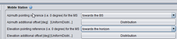
Figure: Mobile station pointing settings
This is intended to reflect random user behaviour with the implementation of a UE with 2 antenna arrays pointing in opposite directions, where only the array which points towards the serving base station is active.
# 3GPP TR 37.840 implementation
A separate implementation of the beamforming antenna in 3GPP TR 37.840 section 5.4.4 is available in the library. This antenna is equivalent to the M.2101 antenna as outlined above, with the exception that there is an additional correlation parameter ρ which allows the user to specify the degree of beamforming correlation (between 0 and 1) according to:
[](https://wiki.cept.org/uploads/images/gallery/2026-04/BiOZDEBkvqgOeXHZ-image.png)
# Beamforming antenna plotting
The antenna pattern for beamforming antennas may be verified using the antenna gain plot as for other antennas (see section x.y.z), with the following additional options for "Link type":
1. Gain envelope: this shows the maximum gain at each angle if φi,etilt and θi,escan are equal to the plot angles (i.e. for horizontal plane θi,escan equals the azimuth angle for each plot, and φi,etilt equals the slice angle; for vertical plane φi,etilt equals the elevation angle for each plot, and θi,escan equals the slice angle). This represents the system link case and indicates the maximum possible gain at each angle, limited by the mechanical constraints of the array.
2. Full pattern: this shows the full beamforming gain across the full range of plot angles, with φi,etilt and θi,escan defined by the user. This represents the interference link case and can be used to verify the shape of the pattern as well as the gain to a victim at a specific offset angle.
Both of these options are illustrated below:
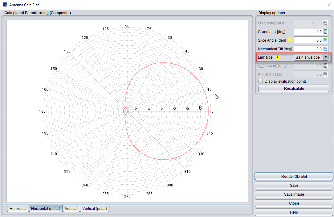
Figure: Beamforming antenna plot using "Gain envelope" mode
Figure: Beamforming antenna plot using "Full pattern" mode, with azimuth beamsteering angle set to 40 degrees
It is also possible to see the beamforming pattern on the individual event results – this can be useful to verify the gain values in a specific direction, as illustrated below:
[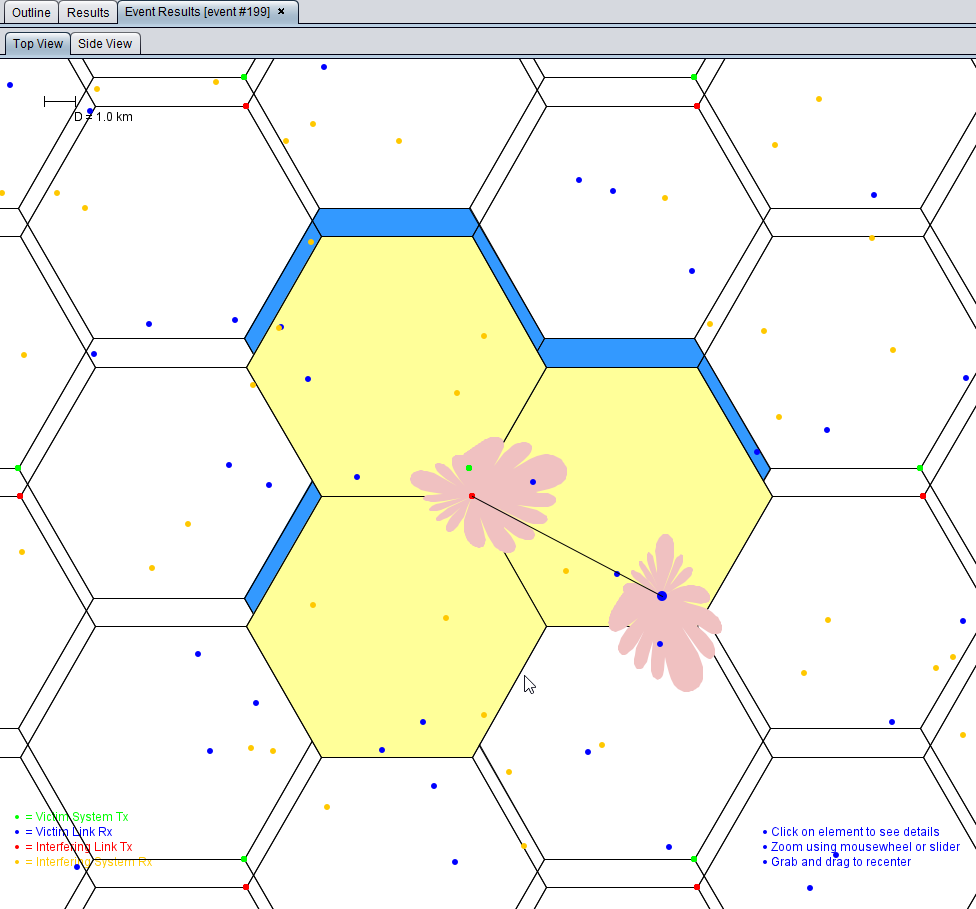](https://wiki.cept.org/uploads/images/gallery/2026-04/Emtq2kJmlDr7ajag-image.png)
Figure: Example of beamforming plots for interference between 2 IMT-2020 networks- ILT BS (red) to VLRUE (blue) - on the Event Results layout
# Beamforming Subarray Active Antenna Systems
## **Active Antenna System**
Active Antenna System are described in Recommendation ITU-R M.2101 and the extended sub-array AAS model with suggested parameters in ITU-R Working Party 5D Chairman's Report in Chapter 4 Annex 4.4 [ITU-RWP5D document 5D/716](https://www.itu.int/dms_ties/itu-r/md/19/wp5d/c/R19-WP5D-C-0716!H4-N4.04!MSW-E.docx "https://www.itu.int/dms_ties/itu-r/md/19/wp5d/c/R19-WP5D-C-0716!H4-N4.04!MSW-E.docx") "Characteristics of terrestrial component of IMT for sharing and compatibility studies in preparation for WRC-23" or 3GPP TR 38.803 Section 5.2.3.2.4. The background information for the AAS model can be found in [ITU-RWP5D document 5D/701-E](https://www.itu.int/md/meetingdoc.asp?lang=en&parent=R19-WP5D-C-0701 "https://www.itu.int/md/meetingdoc.asp?lang=en&parent=R19-WP5D-C-0701").
## **Sub-array AAS plugin parameters**
For the **sub-array AAS plugin** the following parameters can be set:
- **Azimuth additional offset**, see A11.3
- **Elevation additional offset**, see A11.4. The mechanical downtilt depends on the deployment scenario, see in [ITU-RWP5D document 5D/716](https://www.itu.int/dms_ties/itu-r/md/19/wp5d/c/R19-WP5D-C-0716!H4-N4.04!MSW-E.docx "https://www.itu.int/dms_ties/itu-r/md/19/wp5d/c/R19-WP5D-C-0716!H4-N4.04!MSW-E.docx") or 3GPP TR 38.803 Section 5.2.3.2.4.
- **Number of elements in horizontal direction**, **number of subarrays in vertical direction** and **number of elements per sub-array in vertical direction** (positive integers), see example figure below. The figure is from [ITU-RWP5D document 5D/701-E](https://www.itu.int/md/meetingdoc.asp?lang=en&parent=R19-WP5D-C-0701 "https://www.itu.int/md/meetingdoc.asp?lang=en&parent=R19-WP5D-C-0701") showing AAS panel with 8 columns (number of elements in horizontal direction), 4 rows (number of subarrays in vertical direction) and of 3x1 sub-arrays (logical elements).
[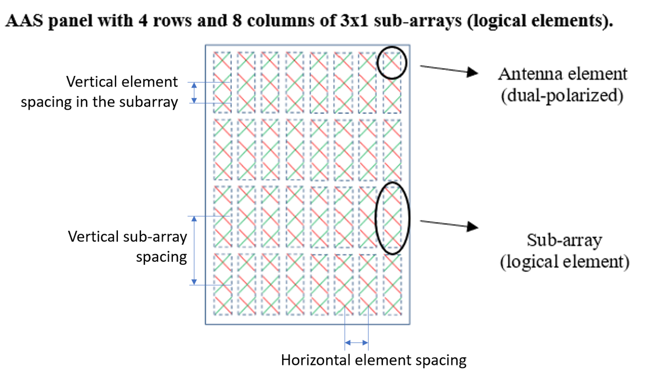](https://wiki.cept.org/uploads/images/gallery/2026-04/RhgjUziqGnSZ7RIe-image.png)
The **horizontal element spacing**, **vertical sub-array spacing** (centre-to-centre) and **vertical element spacing in the subarray** (positive real numbers) are expressed relative to the wavelength (dh,v/). The "vertical sub-array spacing" has to be greater than or equal to the default value corresponding to the product of the "vertical element spacing in the subarray" and the "number of elements per sub-array in the vertical direction".
- **Pre-set sub-array downtilt** is an electrical fixed downtilt in the sub-array. The pre-set sub-array downtilt depends on the deployment scenario, see in [ITU-RWP5D document 5D/716](https://www.itu.int/dms_ties/itu-r/md/19/wp5d/c/R19-WP5D-C-0716!H4-N4.04!MSW-E.docx "https://www.itu.int/dms_ties/itu-r/md/19/wp5d/c/R19-WP5D-C-0716!H4-N4.04!MSW-E.docx") or 3GPP TR 38.803 Section 5.2.3.2.4.
- **Limit coverage range** selected will enable the selection for:
- **Minimum and maximum vertical coverage range** limit for the beamforming. Typical value for macro coverage scenarios are in the range from 0 to -10 degrees and for micro coverage from 0 to -30 degrees (see in [ITU-RWP5D document 5D/716](https://www.itu.int/dms_ties/itu-r/md/19/wp5d/c/R19-WP5D-C-0716!H4-N4.04!MSW-E.docx "https://www.itu.int/dms_ties/itu-r/md/19/wp5d/c/R19-WP5D-C-0716!H4-N4.04!MSW-E.docx") or 3GPP TR 38.803 Section 5.2.3.2.4). They are expressed in SEAMCAT coordinate system with the horizontal plane fixed at zero degree elevation. This setting is independent of the set mechanical antenna tilt. The minimum value must be smaller than the maximum value.
- **Minimum and maximum horizontal coverage range** is typically ±60 degrees from the antenna boresight for a three-sector base station site.
- **Minimise system link gain outside coverage range.** If selected this will effectively set the coupling loss to the UEs that are not within the vertical coverage range to infinite. If not selected, the gain to these UEs will be the resulting gain of the antenna gain envelope with the maximum gain limited to the maximum coverage range.
- For **Element antenna setting,** see below.
- Adjacent channel simulation "use composite antenna pattern" for fully correlated beamforming within the band and adjacent band and "sub-array antenna pattern" for adjacent bands. See TR 37.840 on correlated and uncorrelated beamforming. Beamforming will be less correlated if frequency separation between wanted signal (interferer) and victim increases.
The pre-set typical values in the antenna plugin are for suburban macro case in 1 710-4 990 MHz frequency range. For other configurations see ITU-R Working Party 5D Chairman's Report in [Chapter 4 Annex 4.4](https://www.itu.int/dms_ties/itu-r/md/19/wp5d/c/R19-WP5D-C-0716!H4-N4.04!MSW-E.docx "https://www.itu.int/dms_ties/itu-r/md/19/wp5d/c/R19-WP5D-C-0716!H4-N4.04!MSW-E.docx").
## **Single-element AAS setting** **without multiple elements in sub-array**
For **single-element AAS** **without multiple elements in a** **sub-array** (e.g. for micro cell with 8x8 elements) the following parameters can be used (see in [ITU-RWP5D document 5D/716](https://www.itu.int/dms_ties/itu-r/md/19/wp5d/c/R19-WP5D-C-0716!H4-N4.04!MSW-E.docx "https://www.itu.int/dms_ties/itu-r/md/19/wp5d/c/R19-WP5D-C-0716!H4-N4.04!MSW-E.docx"), Table 9):
- Number of elements in horizontal direction: 8
- Number of subarrays in vertical direction: 8
- Horizontal element spacing: 0.5
Same settings as used in "BeamFormingComposite" antenna plugin for AAS with 8x8 elements. For the sub-array the following values need to be set
- Number of elements per sub-array in vertical direction: 1
- Vertical element spacing in the subarray: 0.7
- Pre-set sub-array downtilt = 0
The elevation additional offset with e.g. -10 degrees.
## **Beamforming element antenna parameters for sub-array AAS**
For the **Beamforming Element Antenna** the following parameters can be set
- **Antenna peak gain** with typical value is 6.4 dBi includes the array ohmic loss of 2 dB and some normalisation of the antenna gain over the sphere. The element antenna gain is per polarisation
- **Azimuth 3dB beamwidth** typical value with 90 degrees for sub-array AAS
- **Vertical 3dB beamwidth** typical value with 65 degrees for sub-array AAS
- **Front to back ratio and side-lobe level limit** can be set to e.g. 30 dB to consider practical limits
##
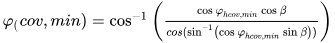
**SEAMCAT equations for limiting sub-array coverage range**
φ: Azimuth angle (0 to 360°)
θ: Elevation angle (-90 to 90°, negative = down)
A: origin point (ILT,ILR,VLT,VLR)
B: target point (ILT,ILR,VLT,VLR)
φhA→B: Antenna azimuth from A to B in horizontal plane
θhA→B: Antenna elevation from A to B with respect to in horizontal plane
φA→B: Transformed antenna azimuth from A to B in the plane perpendicular to boresight
θA→B: Transformed antenna elevation from A to B with respect to boresight
θhcov,min: Minimum vertical coverage range with respect to horizontal plane
θhcov,max: Maximum vertical coverage range with respect to horizontal plane
φhcov,min: Minimum horizontal coverage range in horizontal plane
φhcov,max: Maximum horizontal coverage range in horizontal plane
θcov,min: Minimum vertical coverage range with respect to boresight
θcov,max: Maximum vertical coverage range with respect to boresight
φcov,min: Minimum horizontal coverage range in the plane perpendicular to boresight
φcov,max: Maximum horizontal coverage range in the plane perpendicular to boresight
β: mechanical downtilt (positive = down)
θi,etilt: elevation beam steering angle with respect to mechanical boresight (positive=down)
φi,escan: azimuth beam steering angle in the plane perpendicular to mechanical boresight
Angle transformations:
[](https://wiki.cept.org/uploads/images/gallery/2026-04/EQLwQdqzgTMKdxsf-image.png)
[](https://wiki.cept.org/uploads/images/gallery/2026-04/085hKzkknF1yKOGV-image.png)
[](https://wiki.cept.org/uploads/images/gallery/2026-04/YP08vAyGhYNIIhL2-image.png)
[](https://wiki.cept.org/uploads/images/gallery/2026-04/eWqxME5hkY0MbVd5-image.png)
The beam steering angles are limited to the minimum and maximum coverage angles as follows:
[](https://wiki.cept.org/uploads/images/gallery/2026-04/GG6PeFgAURIVz7L6-image.png)
Alternatively:
[](https://wiki.cept.org/uploads/images/gallery/2026-04/YnJ6smAglnuTUGQa-image.png)
[](https://wiki.cept.org/uploads/images/gallery/2026-04/blfkgXOpUVEOIJre-image.png)
Alternatively:
[](https://wiki.cept.org/uploads/images/gallery/2026-04/gTrk7YUukGV2uz0L-image.png)
[](https://wiki.cept.org/uploads/images/gallery/2026-04/npY3AbNNCNjdnzYx-image.png)
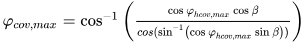
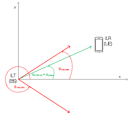
*Figure 1: Elevation example of ILT→ILR link with ILR (UE) within vertical coverage range (θcov,min<θILT→ILR<θcov,max)*
[](https://wiki.cept.org/uploads/images/gallery/2026-04/rmbuoJmPWNQdDw6B-image.png)
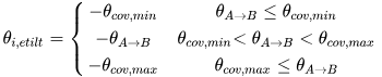
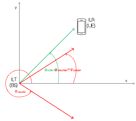
*Figure 2: Elevation example of ILT→ILR link with ILR (UE) outside vertical coverage range (θILT→ILR<θcov,min)*
[](https://wiki.cept.org/uploads/images/gallery/2026-04/RSuZZkEFqZhXJMk4-image.png)
*Figure 3: Azimuth example of ILT→ILR link with ILR (UE) within horizontal coverage range (0≤φILT→ILR<φcov,max)*
[](https://wiki.cept.org/uploads/images/gallery/2026-04/SeHtQnFhoK1qWIaH-image.png)
*Figure 4: Azimuth example of ILT→ILR link with ILR (UE) outside horizontal coverage range (φcov,max≤φILT→ILR<180)*
# POSITIONING
In Section 7.5**.** of this Handbook it is explained cellular network positioning of BSs and MSs which is applicable also to IMT-2020 systems in general.
In addition to cellular positioning mentioned above, for Hybrid system consisting of combination of Macro and micro system and for Micro system, SEAMCAT generates micro cells within the area of macro cell. If macro cell is divided in sectors, micro cells are generated for each sector in system as illustrated bellow.
In hybrid configuration within each Macro BS sector SEAMCAT is generating BS cluster consisting of 2 micro cells of dimeter of 2 km as shown on following Figure.
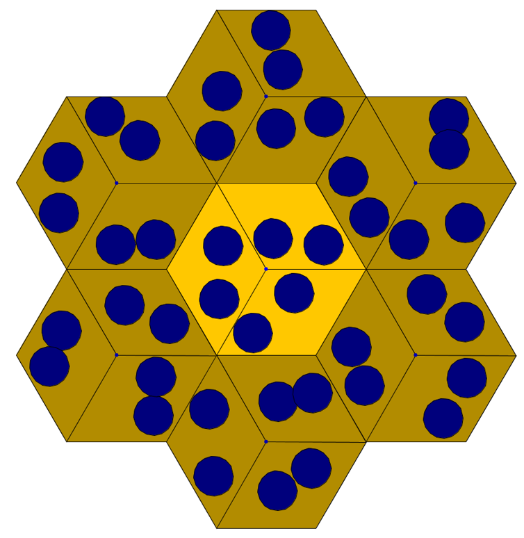
Figure: Example of Hybrid system positioning of Macro and micro cells within IMT-2020 cellular system
# LINK-TO-SYSTEM LEVEL MAPPING
A look up table is used to map throughput in terms of spectral efficiency (bps per Hz) with respect to calculated SINR (= C/(I+N)) (dB) level. Bitrate mapping is connecting radio link quality parameter of SINR to data rates which is then considered in bitrate analysis of reference cell and cellular system in results tab. Bitrate mapping library has predefined functions for IMT-2020 downlink and IMT-2020 uplink determined from (3GPP TR 38.803, section 5.2.7) as shown in Figure below.
However, link level data (bitrate mapping) is user selectable and can be modified depending on the system characteristics and simulation to perform.
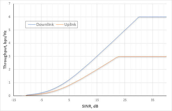
Figure: Throughput vs SINR for IMT-2020 Coexistence Studies (source: 3GPP TR 38.803, section 5.2.7)
# RESULTS
The results tab for the case of IMT-2020 as a victim system and the produced outputs are similar to those for OFDMA (see section [9](https://ecowiki.atlassian.net/wiki/spaces/SH/pages/512134 "https://ecowiki.atlassian.net/wiki/spaces/SH/pages/512134"))