# 8.6.1 Simulation Methodology
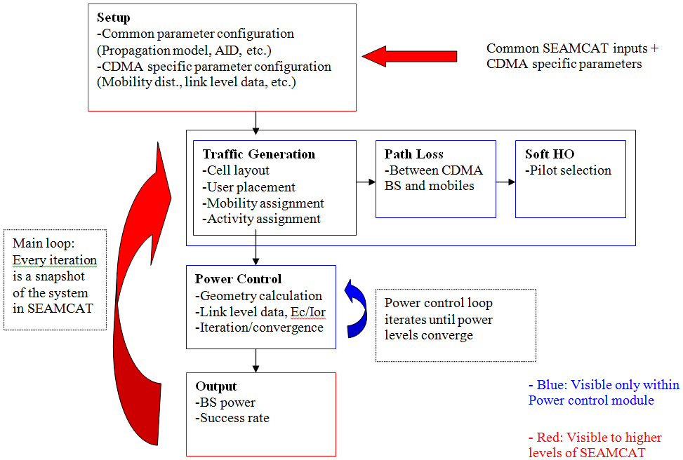
The main goal of the downlink power control in SEAMCAT is to calculate the total BS output power and the success rate (% of calls with no link quality degradation) for a given snapshot of the system. BS output power is a key parameter in the scenarios where CDMA is the interferer. Success rate, on the other hand, is crucial in CDMA victim scenarios. One possible way to analyze the impact of other system interference on CDMA is to compare the success rates in the presence and absence of external interference.
A snapshot of the mutually existing systems is modeled at each event generation in SEAMCAT. Hence, at each event generation the power control algorithm should also be run for the CDMA cell, whether it is the victim or the interferer. This is illustrated in Figure 194. The setup block is inherited from the higher layers of SEAMCAT and consists of initializing the system parameters. The next step involves the generation of traffic for power control, calculation of appropriate path losses within the CDMA cell layout and determination of soft handover states. Power control is then performed by utilizing the link level data via an iterative process. Finally, necessary outputs are generated and fed into the interference calculation modules in SEAMCAT.
[](https://wiki.cept.org/uploads/images/gallery/2026-04/YP7nS30VpVbHEcRd-image.png)
**Figure 194: DL Power Control Simulation Methodology – Overview**
For simplicity, the CDMA downlink power control methodology is described for omni-cells. However, extension to multi-sector cells is straightforward. In a multi-sector configuration, each sector should be treated in the same way a cell is treated in the omni configuration.