8.5 CDMA Link level data
- 8.5.1 CDMA link level system mapping
- 8.5.2 CDMA DL Power Control Methodology (VOICE ONLY)
- 8.5.3 CDMA uplink Power Control Methodology in SEAMCAT (VOICE ONLY)
8.5.1 CDMA link level system mapping
Power control is a crucial mechanism in CDMA mobile radio networks, which needs to be modeled in SEAMCAT. It is a complex process involving various layers of signaling, measurement and modulation/demodulation procedures. It is not feasible to model signaling, link and chip level details of CDMA power control in network level simulations performed by SEAMCAT due to the complexity and CPU time constraints. Hence, it is necessary to adopt the two-step approach employed widely in the industry for the simulation of CDMA based systems.
The first step utilizes link level simulations that model fast fading channels, power control procedures and actual chip level algorithms to generate outputs that map channel power requirements to link quality (e.g. frame erasure rate, FER). Such simulations involve the knowledge of intricate details of the CDMA signaling procedures and modulation/demodulation methods.
Major CDMA vendors develop link level simulations and contribute their results to the standard bodies. Since the link level results are independent of most system level variations (cell sizes, amplifier ratings, antenna types, etc.), they are applicable to a wide variety of network configurations. The second step in the simulation of CDMA involves system level simulations that actually model the CDMA network on a macro scale. Since the required channel power vs. link performance data is available from the link level results, transmit power levels for CDMA channels can be calculated and utilized in the system level modelling of a CDMA network.
The approach described above enables the reuse of link level data to model various network configurations. Furthermore, through the use of the link level data, an accurate power control model is implicitly included in the system level simulations that run at moderate complexity.
The built-in CDMA Link level Data used in DL and UL can be found in Section 13.4.6. SEAMCAT allows you to load your own library too.
8.5.2 CDMA DL Power Control Methodology (VOICE ONLY)
Figure 193 presents the dependency between the condition of a user in the network (the so called geometry), mobile speed and soft handover state of the UE that are needed to map a particular link quality to the channel power requirement.
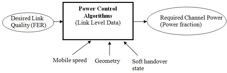
All these factors determine the appropriate mapping of a particular link quality to the channel power requirement. For example, stationary users may require less power than moving users to attain the same link quality. Similarly, users connected to several BS’s at the same time (soft handover) may require less power than users connected to a single BS to achieve the same link quality. Furthermore, users in favorable locations (high geometry) may again require less power than users that are in unfavorable locations (low geometry). Hence, link level data includes different mappings (look up tables) between link quality and required power for different mobile speeds, geometries and soft handover states. Furthermore, in order to remove the dependency on the total BS power (may vary from system to system), the power requirements are reported as normalized power fractions (fraction of the total BS power).
Consequently, the link level data is used in modelling power control in a variety of conditions such as different mobile speeds, geometrical user distributions, soft handover characteristics and amplifier output power ratings. In CDMA Downlink, the link level is a function of Ec/Ior.
8.5.3 CDMA uplink Power Control Methodology in SEAMCAT (VOICE ONLY)
Performance characteristics of individual links to be used in the power control module of SEAMCAT are generated a priori from link level simulations. This usually includes several mappings between requested link quality (e.g. block error rate, BLER) and required transmit power of mobile stations/base stations. For generating such mappings in form of “look up tables”, link level simulations involve multipath fading, physical layer transceiver algorithms, e.g. modulation/demodulation and coding/decoding, as well as power control procedures. Different mulipath fading channels (e.g. the ITU channel models) are used to model various configurations, e.g. indoor, outdoor, pedestrian, vehicular, etc.
In CDMA UL, the sum of received C/I values in two sectors should meet the C/I requirements specified by the link level simulation data. In CDMA Uplink, the link level is a function of Eb/No.