8.3 General settings
- Introduction
- 8.3.1 CDMA general settings
- 8.3.2 Local environment
- 8.3.3 Receiver settings
- 8.3.4 Transmitter settings
- 8.3.5 CDMA uplink
- 8.3.6 CDMA downlink
- 8.3.7 CDMA capacity
- 8.3.8 Propagation Model
Introduction
The General settings tabsheet contains a range of CDMA system parameters as well as some parameters that depend on the modelled direction of CDMA link (uplink vs. downlink). 7 panels characterised the CDMA system. The below graphic represent the CDMA UL when a victim.
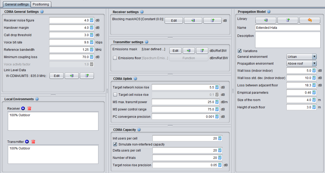
Figure 187: CDMA UL general settings
The only differences with CDMA DL are the following 2 panels (CDMA Downlink and CDMA Capacity).
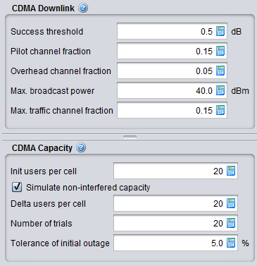
Figure 188: CDMA DL general settings difference with CDMA UL
8.3.1 CDMA general settings
Table 27: CDMA general settings input parameters
|
Description |
Symbol |
Type |
Unit |
Comments |
|
Receiver Noise Figure |
|
Scalar |
dB |
Equipment-specific noise figure of receiver. It is used to calculate the noise floor. See Section1.2.2 |
|
Handover margin |
|
Scalar |
dB |
Specifies the maximum difference between the links in users active list. The actual active-list selection is based on pathloss calculations. |
|
Call drop threshold |
|
Scalar |
dB |
Threshold to determine call drops. It is used by the power control to determine if a user should be dropped when not meeting exact target requirement. |
|
Voice bit rate |
|
Scalar |
kbps |
it is used to calculate the processing gain. See Section 8.7.1. processingGain = 10*log10(systemBandwidth (MHz) / voiceBitRate (kbps) * 1000); |
|
Reference bandwith |
|
Scalar |
MHz |
Bandwidth of the system. It is the same for either UL or DL. |
|
Voice activity factor |
- |
- |
- |
It is set to 1, i.e. 100% (all voice users that are generated are active). It is not editable. |
|
Minimum Coupling Loss |
|
Scalar |
dB |
The minimum path loss. It is used in the calculation of the effective path loss depicted in section 7.6.1 |
|
Link Level Data |
|
Function (X,Y) |
|
Drop-down selection of Link level data look-up functions from Library. It is user's responsibility to choose an appropriate set of data. See Section 8.5 for further details |
8.3.2 Local environment
You can choose the suitable indoor and outdoor ratio for the mobile station to be used by the propagation model. Further details are presented in Section 5.4.3.
8.3.3 Receiver settings
This content of this panel depends whether CDMA system is a victim or an interfering system. If the CDMA is a victim, you will have to set the blocking mask. It is a shared interface with OFDMA.

Figure 192: Cellular panel receiver settings
Table 27: Receiver settings of a cellular system
|
Description |
Symbol |
Type |
Unit |
Comments |
|
Blocking mask/ACS: Receiver frequency response (receiver blocking performance) |
blocking |
Function (X,Y) (MHz) |
dB |
It is similar to the blocking response depicted in Figure 12 except that it is to be set as user defined mode only. In case that the blocking mask is defined with negative values, the parameters Standard desensitization and I/N_target (described below) are used to compute the blocking mask used in the simulations. See section A9.1 (and subsections A9.1.1 to A9.1.3) for the equations |
|
Standard desensitization |
|
|
dB |
It is value of desensitization of the receiver as defined in the standards. |
|
Target I/N |
|
|
dB |
It is the protection criteria used for the simulation. |
8.3.4 Transmitter settings
This content of this panel depends whether CDMA system is a victim or an interfering system. If the CDMA is an interferer, you will have to set the spectrum emission mask and the emissions floor. It is a shared interface with OFDMA.
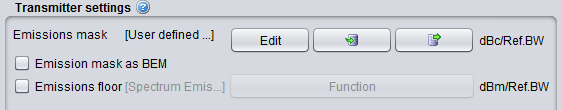 Figure 190: Cellular panel transmitter settings
When defining the Emission Mask (not as BEM) the units of the user defined mask are: Offset (MHz); Mask Values (dBc); Reference Bandwidth (kHz).
When defining the Emission mask as a Block Edge Mask (BEM), SEAMCAT sets to 0 dBi the peak gain of the transmitter antenna and uses the power entries of the Mask as e.i.r.p (already including the gain of the antenna). So, if the Emission mask is defiend as BEM, the units of the user defined mask are: Offset (MHz); Mask Values (dBm e.i.r.p.); Reference Bandwidth (kHz).
8.3.5 CDMA uplink
This is only available if CDMA UL selected.
|
Description |
Symbol |
Type |
Unit |
Comments |
|
Target network noise rise |
|
Scalar |
dB |
Specific level of noise that the network is willing to handle, when this level is reached it starts removing UEs to reduce its noise level |
|
cell noise rise selection |
|
Boolean |
- |
Select the algorithm that allow the cell selection based on a noise rise increased. If selected, then the measure of the noise rise per each cell is considered and the algorithm, recursively, tries to identify the number of affected cells due to a single source/cluster of interferers and remove users. If not selected, then the measure of the noise rise over the whole network is considered (See Section 8.7.6 for details) |
|
Target cell noise rise |
|
Scalar |
dB |
Only available when Cell noise rise selection is active. It is set to 0.1 dB by default. The “cell noise rise” algorithm will assess whether to drop users from any cell in which the noise rise exceeds the threshold indicated above. The default value of 0.1 dB has been chosen to ensure that the analysis does not disregard any cases of interfered cells, since users may also be dropped as the consequence of a low noise rise. |
|
MS maximum transmit power |
|
Scalar |
dB |
Maximum transmit power of the MS (i.e. the UE) |
|
MS power control range |
|
Scalar |
dB |
Span of the fluctuation of the power |
|
PC convergence precision |
|
Scalar |
dB |
In the uplink, each mobile station perfectly achieves the target C/I, Eb/N0_target, during the power control loop convergence, assuming that the maximum transmit (TX) power, max_MS_Tx_Pw, is not exceeded. Those mobile stations not able to achieve Eb/N0_target after convergence of the power control loop are considered in outage (i.e. they are dropped). The power control loop is considered to converge when all mobile stations are within the max_MS_Tx_Pw and their Tx power is adjusted by less than the “PC convergence precision” value for the last power balancing iteration. |
8.3.6 CDMA downlink
This panel is available only if CDMA DL selected.
|
Description |
Symbol |
Type |
Unit |
Comments |
|
Success threshold |
|
Scalar |
dB |
Threshold to determine perfect link quality. |
|
Base Station Pilot Channel Fraction |
pilot_frac |
Scalar |
- |
Fraction of max BS power allocated to pilot. |
|
Base Station Overhead Channel Fraction |
Overhead_frac |
Scalar |
- |
Fraction of max BS power allocated to overhead channels (paging, etc.). |
|
Base Station maximum Broadcast Power |
|
Scalar |
dBm |
maximum Broadcast Power |
|
Base Station maximum traffic channel fraction |
|
Scalar |
- |
Fraction of the maximum allowable broadcast power (per traff. chan. per BS). The maximum allowable traffic channel power is compared to the calculated transmit traffic channel power levels with respect to the Ec/Ior link level data for iterative adjustment in the DL power control. |
8.3.7 CDMA capacity
The capacity of the simulated system (i.e. how many mobiles per cell should be generated in the system) is dependent on all other settings and cannot always be easily deducted from these. Therefore SEAMCAT has a feature that allows for automatic determination of capacity. This is also known as simulation of non interfered capacity and is enabled by default.
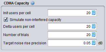
In CDMA UL, the number of optimised users is being re-calculated for each event. It is recommended to run the "simulate non-interfered capacity" so that SEAMCAT can provide a "best" optimised value, this will optimise the computation time afterwards. If you are using another number you risk to create an overhead in your computation time without any change in the output results.

|
Description |
Symbol |
Type |
Unit |
Comments |
|
Simulate non interfered capacity |
- |
Boolean |
- |
Toggles automatic capacity finding. If the option Simulate non-interfered capacity is checked, then the system will automatically simulate the 'optimal' number of the mobiles for given system configuration (type of system, bandwidth, cell sizes, etc). The optimum finding algorithm is developed to establish the loading that would correspond to approx. 80% of maximum system capacity. If this option is unchecked, you are free to set a constant user-defined average number of mobile users per cell especially if the optimal capacity for the current scenario is known (this is often the case when running consecutive simulations with the same system) there is no need to simulate – as the simulation process can be quite lengthy. When this checkbox is disabled SEAMCAT uses the value entered in 2 – “Users per cell” as the capacity per cell. |
|
Init users per cell |
- |
Scalar |
- |
If capacity simulation is enabled this indicates the starting point of the simulation. Selecting the right starting point can speed up the capacity finding. If capacity simulation is disabled the value in this field is the actual value used by SEAMCAT. SEAMCAT does NOT change this input value into the result of the simulation! Users per cell is equal to UE per Base Station. SEAMCAT consider each Base station as its own cell. |
|
Delta users per cell |
|
Scalar |
- |
When SEAMCAT tries to find the optimal capacity it adjust the number of UEs per cell starting with this value. A proper value here can speed up capacity finding. |
|
Number of trials |
|
Scalar |
- |
When finding the optimal capacity SEAMCAT runs this (i.e. Number of trials) many snapshots of every value of UEs per cell before deciding whether or not the current value is the optimal capacity. Generally larger numbers mean greater precision but also longer time needed by the algorithm. |
|
Target noise rise precision |
|
Scalar |
dB |
Uplink only – the precision used when comparing the noise rise of the filled system with target noise rise set under the “CDMA Uplink” panel |
|
Tolerance of initial outage |
|
Scalar |
% |
Downlink only – The tolerance of initial outage is the percentage of UEs that can be dropped before SEAMCAT determines that the tested number of UEs cannot fit into the system (i.e. 20 user_per_cell * 19 BS = 380 UEs, if 5% or less of 380 UEs are dropped, the system is considered able to handle/service 20 UEs per cell). SEAMCAT will adjust the value of UEs per cell untill a value is found which in 80% of the specified number of trials is able to handle the tested number of UEs per cell.This parameter allows for UEs in “extreme” pathloss situations to be “ignored” from the optimal capacity finding. |
8.3.8 Propagation Model
You can choose the suitable propagation model to be applied when calculating signal loss along the transmitter and the receiver path. A choice and settings of propagation models are presented in ANNEX 17:.