# 6.2 Simulating spectrum sensing
The manual sets out how SEAMCAT can be used for spectrum sensing where the interfering devices (ILT) try to detect the presence of protected services (e.g. the VLT) transmitting in each of the potentially available channels. Spectrum sensing essentially involves conducting a measurement within a candidate channel to determine whether any protected service is present and transmitting. When a channel is determined to be vacant, sensing is typically applied to adjacent channels to identify what constraints there might be on transmission power, if any.
A key parameter for spectrum sensing is the detection threshold that is used by a cognitive device to detect the presence or the absence of a protected service’s transmission. If it detects no emission above this threshold in a channel, the white space device (WSD, i.e. the It) is allowed to transmit, otherwise the WSD keeps silent or look into other channels. You can study this phenomenon in SEAMCAT, which enables multiple cognitive radio systems. The cognitive radio feature mainly introduces the detection threshold and the selection of the operating frequency of the WSD.
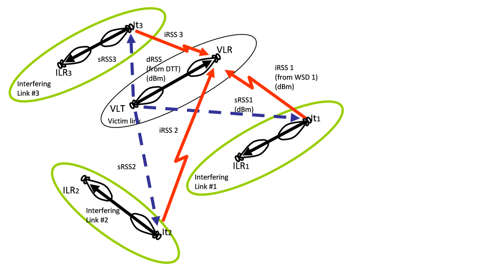
In SEAMCAT, the CRSs are assumed to be the interferers. A SEAMCAT workspace will contain only 1 victim system and 1 or many interferers. It is possible to assess the aggregated impact of interferers that can be either CR devices or not. The scenario allows the impact of spectrum sensing to be investigated where a cognitive radio device is activated nearby a victim system. Both the victim and the interfering dialogue interface should be filled to enable spectrum sensing in SEAMCAT. Figure 157 illustrates that the introduction of spectrum sensing requires an extra budget link called sensing Received Signal Strength (sRSS) which represents the signal which is transmitted by the VLT and is sensed by the It. Note that the It acts as a transceiver, meaning that when the energy is sensed though the bandwidth of the sensing device (i.e. the It), it is acting as a receiving device.
The sRSS (considering the unwanted mask of the DTT) at the channel *m* is calculated as described in ANNEX 6:.
It is assumed that the frequency of the interfering cognitive radio device is dependent on the frequency range defined for the victim. This means that when the CR module is activated, the interfering frequency function dialogue box is de-activated (#4 of Figure 231). Depending on how the victim frequency is defined (i.e. constant, discrete or distributed between fmin and fmax). SEAMCAT only allows the use of the following distributions: Constant, User defined, Uniform, User defined (stair).
[](https://wiki.cept.org/uploads/images/gallery/2026-04/vjoR2mdSaQSAdgka-image.png)
**Figure 157: Illustration of 3 cognitive radio systems (WSD) and a victim system (sRSS is in blue)**