Introduction
It can be the VLR or the ILR as illustrated in Figure 143.
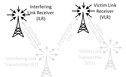
Figure 143: Receiver illustration as VLR or ILR
The receiver consists of 5 panels (Figure 144); Receiver identification, antenna pointing, antenna patterns identification, reception characteristics and interference criteria.
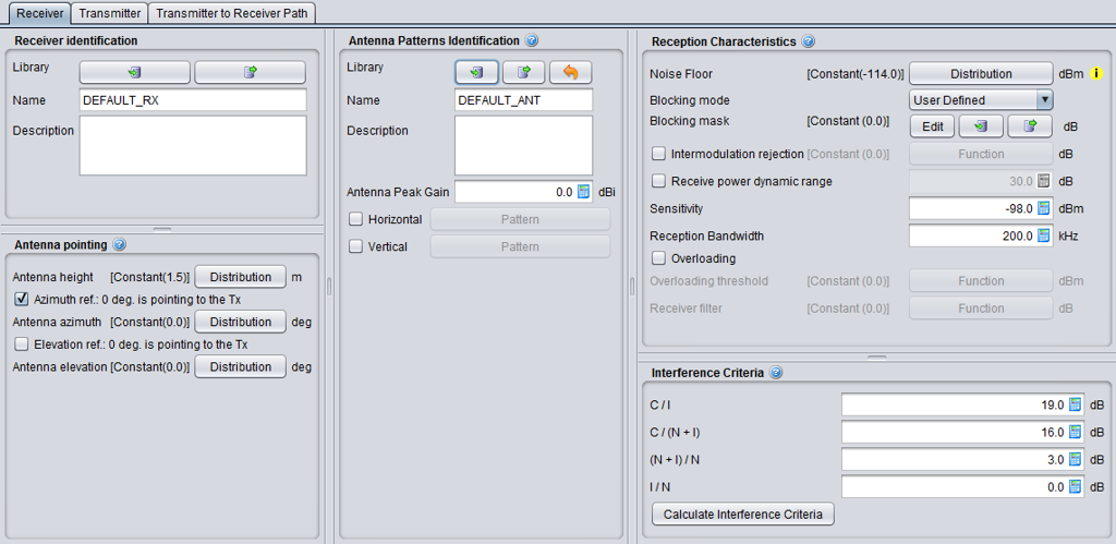
Figure 144: Receiver GUI