Introduction
3 elements form the path between the VLR and the VLT or the ILR and ILT as illustrated in Figure 148.
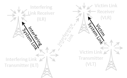
Figure 148: Transmitter to Receiver Path illustration

Figure 149: Transmitter to Receiver Path GUI
3 elements form the path between the VLR and the VLT or the ILR and ILT as illustrated in Figure 148.
Figure 148: Transmitter to Receiver Path illustration
Figure 149: Transmitter to Receiver Path GUI