5.4 Transmitter to Receiver Path
- Introduction
- 5.4.1 Relative location
- 5.4.2 Coverage radius
- 5.4.3 Local environment
- 5.4.4 Propagation Model
Introduction
3 elements form the path between the VLR and the VLT or the ILR and ILT as illustrated in Figure 148.
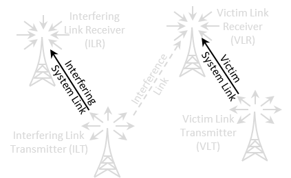
Figure 148: Transmitter to Receiver Path illustration

Figure 149: Transmitter to Receiver Path GUI
5.4.1 Relative location
See ANNEX 12: for further details on the algorithm and conventions.

|
Description |
Symbol |
Type |
Unit |
Comments |
|
Correlation distance |
- |
Boolean |
- |
When checked, the only the Delta X and Y are editable. |
|
Delta X |
X |
Distribution |
Km |
Horizontal distance between the transmitter and receiver. It can be used to shift horizontally the distributed receivers. |
|
Delta Y |
Y |
Distribution |
Km |
Vertical distance between the transmitter and receiver. It can be used to shift vertically the distributed receivers. |
|
Path azimuth |
- |
Distribution |
Degree |
Horizontal angle for the location of the Rx respect to the Tx. If constant, the Rx’s location will be on a straight line. If not, the location of the Rx will be on an angular area. (See Annex A12.3) |
|
Path distance factor |
- |
Distribution |
- |
Distance factor to describe path length between the Tx and the Rx. If the path factor is constant, the Rx will be located on a circle around the Tx. (See Annex A12.2) |
|
Use of polygon |
- |
Boolean |
- |
When this is checked, you can select other shape of deployement than the default circle |
|
Shape of the polygon |
- |
Boolean |
- |
You can select between hexagon (6 sides), heptagon (7 sides), Octagon (8 sides), Pentagon (5 sides), Rectangle (4 sides) and Triangle (3 sides) |
|
Turn CCW |
- |
Distribution |
Degree |
Allows to rotate counter clock wise the selected polygon |
5.4.2 Coverage radius
A coverage radius is calculated for both the victim link and the interfering link. It is the 
for the victim link (VLR-VLT) and the  for the interfering link (ILR-ILT) (see Annex A13.1). The receivers will be randomly deployed within the area centred on the transmitter and delimited by the coverage radius if the non-correlated option is selected.
Three different modes are available for calculating the maximum radius .
-
User-defined radius allows directly entering the maximum radius (See Annex A13.1.1);
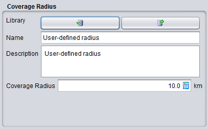
Figure 151: User-defined coverage radius dialog box
Table 16: Description on User-defined coverage radius
|
Description |
Symbol |
Type |
Unit |
Comments |
|
Coverage radius |
Rmax |
Scalar |
km |
The coverage radius defines the coverage of the system, i.e. the maximum distance between an ILT and a ILR or between a VLT and a VLR.
|
- The noise-limited network option will calculate the coverage radius based on the formula for noise-limited network. If this option is chosen, a set of input boxes will appear below allowing the user to enter specific parameters required for this calculation. In this case it is considered that the coverage of the transmitter is limited only by propagation losses and other elements in thelink budget, with received signal operating at the sensitivity limit. The details of the calculation are given in Annex A13.1.2.
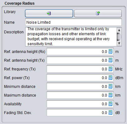
Figure 152: Noise limited network coverage radius dialog box
The coverage radius in the noise-limited network is defined by the parameters of Table 17. Note that the input parameters for the Noise-limited network interface are set to zero by default in order to independently define the radius from some parameters set elsewhere in the link.
|
Description |
Symbol |
Type |
Unit |
Comments |
|
Reference antenna height (receiver): |
h0 |
Scalar |
m |
The height used for coverage radius calculations. If a distribution is used to define the real height, the coverage radius would be different in each trial, here the value may be fixed. |
|
Reference antenna height (transmitter): |
h0 |
Scalar |
m |
The height used for coverage radius calculations. |
|
Reference frequency |
fVLR |
Scalar |
MHz |
|
|
Reference power |
PVLT |
Scalar |
dBm |
|
|
Minimum distance |
|
|
km |
|
|
Maximum distance |
|
|
km |
|
|
Availability |
|
|
% |
|
|
Fading standard deviation |
|
|
dB |
|
|
Reference percentage of time |
|
|
% |
|
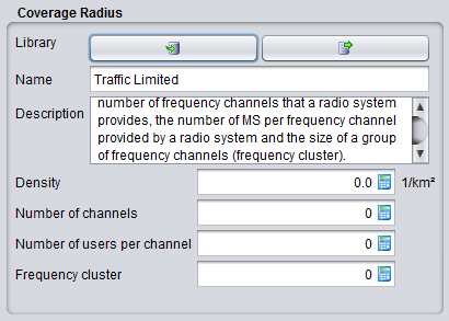
Traffic-limited network option will calculate the coverage radius, based on the formula for traffic-limited network. If this option is chosen, a set of input boxes will appear below allowing user to enter specific parameters required for this calculation (See Annex A13.1.3).
The consistency of this parameter should be verified against the sensitivity, so that if a receiver is placed at given distance (e.g. at the maximum coverage radius) the received power is higher than the sensitivity for a reasonable percentage of occurrences (availability).
5.4.3 Local environment
The percentage of transceivers being indoor and outdoor can be selected thanks to this panel. It will work in combination with the chosen propagation model that you will select. By default the transmitter and receiver are located outdoor. For each elements of the link, it is possible to add  or remove
  a probability of indoor.
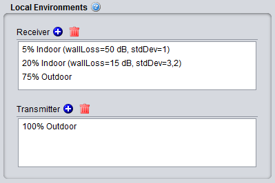 Figure 154: Example of setting up the outdoor/indoor ratio
You can edit the field by double cliking
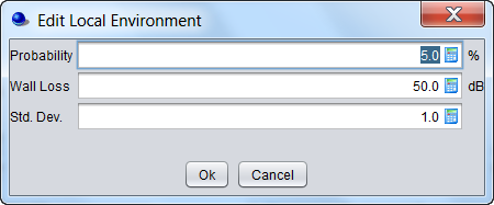 Figure 155: Graphical interface to edit the probability, wall loss and associated standard deviation
Table 19: Local environment and wall loss
|
Description |
Symbol |
Type |
Unit |
Comments |
|
Local environment: Receiver |
Indoor/ outdoor |
- |
- |
Environment of the receiver antenna: outdoor, indoor It is used for both VLR and ILR. |
|
Local environment: Transmitter |
Indoor/ outdoor |
- |
- |
Environment of the transmitter antenna: outdoor, indoor It is used for both VLT and ILT. |
|
Probability |
- |
Scalar |
% |
Probability that a Tx or Rx is located indoors or outdoors. |
|
Wall loss |
or |
Scalar |
dB |
Attenuation of external walls separating indoor and outdoor propagation environments. This parameter is associated to the selected propagation model. |
|
Std. dev. |
or |
Scalar |
dB |
Wall loss stdandard deviation (indoor - outdoor) |
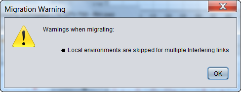
Note that when opening a workspace created prior to SEAMCAT version 5, all settings are mapped to the current SEAMCAT version running on your machine. As the parameter local environment didn’t exist before version 5, a warning may appear indicating that “local environments are skipped for multiple interfering links”. This means that SEAMCAT was not able to automatically set the parameters of the local environments (most likely due to a scenario with multiple interferers). Therefore, there is a need to edit the local environment manually.
5.4.4 Propagation Model
A suitable propagation model can be selected to be applied when calculating signal loss along the path between transmitters and receivers. Further information on propagation models are presented in detail in ANNEX 17.