5.2 Receiver
- Introduction
- 5.2.1 Receiver identification
- 5.2.2 Antenna pointing
- 5.2.3 Antenna patterns identification
- 5.2.4 Reception characteristics
- 5.2.5 Interference criteria
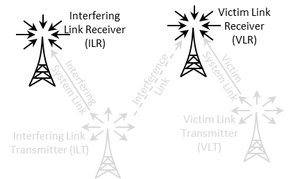
Introduction
It can be the VLR or the ILR as illustrated in Figure 143.
The receiver consists of 5 panels (Figure 144); Receiver identification, antenna pointing, antenna patterns identification, reception characteristics and interference criteria.
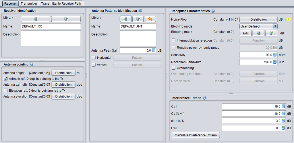
5.2.1 Receiver identification
This panel is a common interface that is reused in all other radio system.
|
Description |
Symbol |
Type |
Unit |
Comments |
|
Library
|
- |
Library |
- |
Allows to import/export the receiver characteristics from/to the library to/from the workspace |
|
Name |
- |
Free text |
- |
Freely chose a name and a description for the receiver. Remember that the settings can be exported to the library, so it is important that the description is accurate enough when reusing or sharing it. |
|
Description |
- |
Free text |
- |
5.2.2 Antenna pointing
This panel is a common interface that is reused in other radio system. It contains all information relative to the antenna other than the radiation pattern.
Table 10: Receiver antenna pointing GUI
|
Description |
Symbol |
Type |
Unit |
Comments |
|
Antenna height |
h |
Distribution or Scalar |
m |
See ANNEX 11:. |
|
Azimuth ref. 0 deg is pointing to the Tx |
- |
Boolean |
- |
When selected, the antenna (i.e. for an antenna azimuth distribution of 0°) is pointing by default at the VLT. If not selected, it looks EAST. |
|
Antenna azimuth: Antenna alignment horizontal tolerance |
dH |
Distribution or Scalar |
degree |
This is the angle between the Rx main beam and the direction to Tx. E.g. if antenna azimuth=0, the Rx and Tx antennas are strictly aligned in the horizontal plane, see ANNEX 11:. |
|
Elevation ref. 0 is pointing to the Tx |
- |
Boolean |
- |
When selected, the antenna (i.e. for an antenna elevation distribution of 0°) is tilted by default towards the VLT. If not selected, it is set horizontal. |
|
Antenna elevation: Antenna alignment vertical tolerance |
dV |
Distribution or Scalar |
degree |
This is the vertical angle between the Rx main beam and the direction towards Tx. E.g. if antenna elevation=0, the Rx and Tx antennas are strictly aligned in the vertical plane, see ANNEX 11: on p. 312. |
5.2.3 Antenna patterns identification
This panel is a common interface that is reused in all other radio system. It contains all information relative to the antenna radiation pattern:
|
Description |
Symbol |
Type |
Unit |
Comments |
|
Library
|
- |
Library |
- |
Allows to import/export the antenna pattern from/to the library to/from the workspace. |
|
Name |
- |
Free text |
- |
|
|
Description |
- |
Free text |
- |
|
|
Antenna peak gain |
G |
Scalar |
dBi |
Antennae are implemented as plugins, therefore see ANNEX 11: as separate guidance on the the radiation pattern. |
|
Horizontal |
- |
Pattern |
- |
Pattern selection. See working range in ANNEX 11:. |
|
Vertical |
- |
Pattern |
- |
Pattern selection. See working range in ANNEX 11:. |
5.2.4 Reception characteristics
This panel consists in setting of the receiver characteristics of the generic system:
|
Description |
Symbol |
Type |
Unit |
Comments |
|
Noise floor: define a distribution of the noise floor |
N |
Distribution or Scalar |
dBm |
See section 1.2.3 for further details
|
|
Blocking mode
|
- |
Boolean |
- |
Blocking mode and associated blocking mask |
|
Blocking response: Receiver frequency response (receiver blocking performance) |
blocking |
Function (X,Y) (MHz) |
dBm or dB depend. on mode |
Receiver mask attenuation (positive or negative values depending on the chosen blocking mode, see below) versus frequency, see ANNEX 8: |
|
Intermodulation rejection: Intermodulation response (intermodulation interference) |
intermod |
Function (X,Y) (MHz) |
dB |
Receiver mask at the intermodulation frequency. (see Annex A5.3 for further details) |
|
Receive power dynamic range
|
Pcmax |
Scalar |
dB |
Used in the calculation of the dRSS. It is the maximum range of the received power that the VLR can accept, in terms of the maximum receive power over the VLR’s sensitivity threshold. If the trialled dRSS value exceeds sens+Pcmax , the dRSS is set to the latter value. See ANNEX 14:. |
|
Sensitivity
|
sens |
Scalar |
dBm/VLR reception bandwidth |
Sensitivity of the receiver. See Section 1.2.4 |
|
Reception bandwidth: Operating bandwidth |
B |
Scalar |
kHz |
Bandwidth of the receiver. |
|
Overloading |
- |
Boolean |
- |
When selected, the overloading calclulation is performed. See Annex A5.4 for further details. |
|
Overloading threshold
|
Oth |
Function (X,Y) (MHz) |
dBm |
It is the maximum interfering signal level close to which the receiver loses its ability to discriminate against interfering signals at frequencies differing from that of the wanted signal |
|
Receiver filter |
Rx_filter |
Function (X,Y) (MHz) |
dB |
Filtering of the receiver (if any). The filtering of the receiver is by default 0 dB (similarly to the default blocking filtering value). It is used in connection with the overloading calculation. |
5.2.5 Interference criteria
Section 1.4 presented the concept of interference criteria (C/I, C/(N+I), (N+I)/N, I/N) when the victim is a generic system. The consistency between these values falls under the responsibility of the user. It should be noted that only one criterion is used at a time in the final interference calculation.
It is important to remember that these parameters are also used in the evaluation of the two blocking modes (Protection ratio and Sensitivity) as presented in See section 1.4.5.
SEAMCAT performs a consistency checking between the interference criteria as explained in ANNEX 3:.
|
Description |
Symbol |
Type |
Unit |
Comments |
|
Interference criteria |
C/I C/(N+I) (N+I)/N I/N |
Scalar |
dB |
At least one of these criteria should be defined: (C/I, C/(N+I), (N+I)/N, I/N). |
|
Calculate interference criteria |
- |
calculator |
- |
This feature allows the evaluation of the consistency between the entered interference criteria (C/I, C/(N+I), (N+I)/N, I/N) and proposes alternative values that can be selected to ensure consistency between them. |
The “calculate interference criteria” is a user friendly calculator for the interference criteria. It avoids conspicuous calculations, increases the transparency and avoids consistency check warnings because of the use of inconsistent sets of values.
The calculation and selection of a consistent set of interference criteria is implemented. The calculator opens with the existing values in the interference criteria fields of the workspace. A checkbox (default: ON) allows to force the consistency of the C/(N+I) value with the workspace, i.e. the values ‘Noise floor’ and ‘Sensitivity’. The relation between the values is given in the formula C/(N+I) [dB] = Sensitivity [dBm] – Noise floor [dBm]
The Interference Criteria Calculator displays all possible sets of consistent interference criteria rounded to two decimals. The same set is displayed only once. As a consequence of rounding, the displayed sets are differ at least 0.01 dB in one of the four values.
When you select the column of values you want and click ok, the values are copy/pasted to the “Interference criteria” panel.
