4.4 iRSSoverlaoding
The following graphics presents the input parameters to activate when the overloading mechanism is to be simulated.

The overloading mask is expressed in power (dBm) versus frequency offset (MHz) and is defined as a function in SEAMCAT.

Figure 108: Setting of the overloading mask in SEAMCAT
The filtering of the receiver is expressed in power (dB) versus frequency offset (MHz) and is defined as a function in SEAMCAT (see Figure 109). It is set by default to a constant value of zero.
Note that if the blocking attenuation mode in user-defined and the overloading feature have been selected, then a consistency check will remind you that the actual blocking response and the receiver filter are the same element and they should not be accounted twice.

Figure 109: Example of filling the Rx filter function
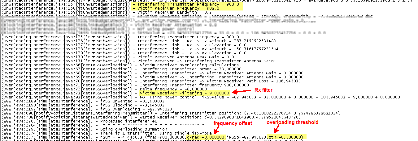
When a simulation is run the following results are extractable (see Section 12.3.4 for further details)
As an example, this means that for the following overloading mask presented in Figure 3 with a victim frequency of 908 MHz and an interfering frequency of 900 MHz, the delta frequency (i.e. frequency offset) is -8 MHz with an overloading treshold of -8.5 dB and a Rx filter value of 9 dB. This can be found from the log file as shown below in Figure 110.