# 4.1 iRSSunwanted
The following parameters should be changed in the simulation: (i) the interferer operates at 1000.3 MHz and (ii) outside the emission bandwidth, the attenuation is -23 dBc/200 kHz.
The corresponding power may derived using the known equation:
*(Eq. 20)*
[](https://wiki.cept.org/uploads/images/gallery/2026-04/LkF1IdJS3brKgBOD-image.png)
Then, in this example, outside the emission bandwidth (offset between –0.1 MHz and -1 MHz and between 0.1 MHz and 1 MHz), the power is equal to:
[](https://wiki.cept.org/uploads/images/gallery/2026-04/0yrjzOgCvrfjrVnp-image.png)
The complete unwanted emission mask is provided in the below figure.
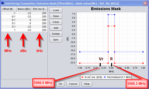
**Figure 99: Unwanted emission mask**
Using the previous assumptions, it is possible to derive the interfering power received by the Victim link receiver *within its bandwidth* as described in ANNEX 5: on page 274. This is called the iRSSunwanted:
*(Eq. 21)*
[](https://wiki.cept.org/uploads/images/gallery/2026-04/fjRmJOEE13LTjEVE-image.png)
[](https://wiki.cept.org/uploads/images/gallery/2026-04/qIi4YENJnbtoDGZm-image.png)
[](https://wiki.cept.org/uploads/images/gallery/2026-04/lDDTr6hKX9oaPRrP-image.png)
This can be checked by running a simulation and displaying the iRSSunwanted signal as depicted in Figure 100.
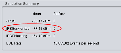Figure 100: Mean iRSSunwanted

**In this example there is no bandwidth correction factor to be applied to the calculation of the iRSSunwanted since the VLR bandwidth and the ILT reference bandwidth have the same value (i.e. 200 KHz).**
**Examples of correction bandwidth can be found in section 3.3.8**