3.2 Calculating the dRSS
- 3.2.1 Victim link
- 3.2.2 System to be a victim
- 3.2.4 Transmitter
- 3.2.5 Positioning the VLT vs VLR
- 3.2.6 Selecting the propagation model
- 3.2.7 Calculating the dRSS by hand
- 3.2.8 Export/import your system to library
- 3.2.9 Selecting the victim in the Scenario
3.2.1 Victim link
The victim parameter characteristics summarised in Table 6 should be entered into SEAMCAT.
|
Parameters |
Value |
Units |
|
Operating Frequency |
1000 |
MHz |
|
Transmitter power |
30 |
dBm |
|
Receiver bandwidth |
200 |
kHz |
|
Tx and Rx antenna type |
Omni directional |
|
|
Tx and Rx antenna gain |
9 |
dBi |
|
Tx and Rx antenna height |
30 |
m |
|
C/I protection criteria |
19 |
dB |
|
C/(N+I) protection criteria |
16 |
dB |
|
(N+I)/N |
3 |
dB |
|
I/N |
0 |
dB |
|
Noise floor |
-110 |
dBm |
Each simulation workspace contains one and only one victim link.
3.2.2 System to be a victim
In order to set up a workspace, the first step is to set the system that will be used as victim: set the characteristics of the receiver (that will be the victim link receiver (VLR)) and the transmitter (that will be the victim link transmitter (VLT)).
System characteristics can be directly edited in the system tab. This is illustrated in the figure below.

Figure 65: Access to the system environment
For example, a generic system can be selected from the “import system from library button” as shown Figure 67.
 Figure 66: Import system from library button

Figure 67: Selecting a system from library
First, let set the frequency of the victim. The frequency can be changed from 900 MHz (default value) to 1000 MHz as described in Figure 68. In this example a constant value is considered, but in principle any type of distribution can be selected.
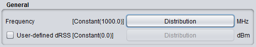 Figure 68: Example of setting up the operating frequency
3.2.4 Transmitter
Set now the victim link transmitter by selecting the transmitter tab

Figure 74: Selecting the transmitter tab
The parameters should be filled as follows:
-
The power is 30 dBm; (#1 of Figure 75)
-
An omni-directional antenna of 9 dBi is used;
-
The antenna height is 30 m.
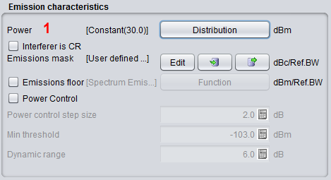
Figure 75: Example of setting up the victim link transmitter
3.2.5 Positioning the VLT vs VLR
Define now the positions of transmitters and receivers of the victim link.

Figure 76: Selecting the Tx to Rx path tab
SEAMCAT allows defining the locations of the Victim link receiver and the Victim link transmitter in a fixed manner (correlated) or following some distribution (uncorrelated) as summarised in Figure 77. The input parameters are detailed in section 5.4, and the algorithms are detailed in ANNEX 13:
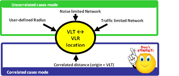
Figure 77: Summary of the VLT ↔ VLR location capability in SEAMCAT
In this exercise, set the distance between the VLT and the VLR as fixed (correlated distance) (x = y = 2 km) as illustrated in Figure 78.
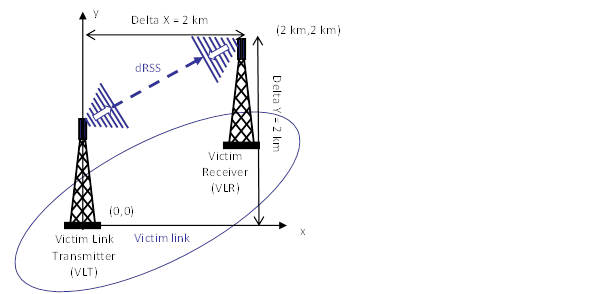
Figure 78: Distance between the Victim link transmitter and the Victim link receiver (Victim Link)
It is assumed that the Tx and Rx are both outdoor as shown in Figure 79.
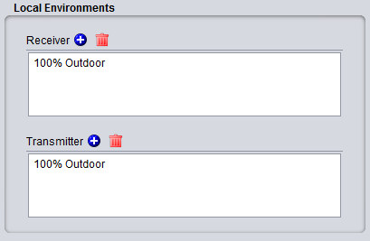
Figure 79: Example of setting up the outdoor/indoor ratio
For this, select the correlated distance option of SEAMCAT as shown in Figure 80. In SEAMCAT, the origin of the coverage radius (see ANNEX 13:) is the transmitter (this is also reminded in the GUI) of the link.

Figure 80: Illustration of the correlated distance in SEAMCAT
3.2.6 Selecting the propagation model
Since both the transmitter and the receiver characteristics and the location between the two have been defined, the propagation model needed for the simulation can be now selected.
To simplify this task, let us assume that the free space model is used to calculate the attenuation between the Victim link receiver (VLR) and the Victim link transmitter (VLT).
In addition, the Variation should be disabled as shown in Figure 81.
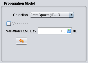
Figure 81: Example of setting up the free space propagation model for Step 1
3.2.7 Calculating the dRSS by hand
Using the Free space equation, the power received by the Victim link receiver (dRSS) can be easily derived:
 (Eq. 17)


Keep this calculation in mind, as it will be compared with what SEAMCAT calculates in the following sections.
3.2.8 Export/import your system to library
When setting the system is complete, it is possible to export it to the library, so it can be reused in a future point of time.
 Figure 82: Example of importing/exporting a system to library
3.2.9 Selecting the victim in the Scenario
Now it’s time to create the victim link. The only thing needed is to select a system to be used as victim link as shown in (#1) of Figure 83 under the “scenario” tab.
Note that the frequency field at the “scenario” tab level overwrites what was predefined at “system” tab level (#2).

Figure 83: Setting the system of your choice to be the victim link in the “scenario” tab