13 Library of scenario elements
- 13.1 Library overview
- 13.2 Import / export a library element in/from a workspace
- 13.3 Edit and share library element
- 13.4 Library elements
- 13.4.1 System elements
- 13.4.2 Spectrum emission mask elements
- 13.4.3 Receiver blocking mask elements
- 13.4.4 Receiver elements
- 13.4.5 Transmitter elements
- 13.4.6 CDMA Link level data
- 13.5 Plugins Library
13.1 Library overview
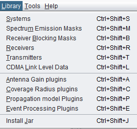
SEAMCAT library is a useful tool for creating and storing various elements that are part of a wireless system so that they can be re used at a later point of time. The SEAMCAT library contains the following elements:
-
Systems and System Plugins (SP)
-
Spectrum Emission Masks (SEM)
-
Receiver Blocking Masks (RBM)
-
Receivers
-
Transmitters
-
CDMA Link Level Data
-
Antenna Gain Plugins (AGP)
-
Coverage Radius Plugins (CRP)
-
Propagation Model Plugins (PMP)
-
Event Processing Plugins (EPP)
Note that technical library management functions are available regardless of whether a simulation workspace has been loaded or not. The library can be saved in a separate file too so that you can also share them.
13.2 Import / export a library element in/from a workspace
Modification of existing (default) library elements as well as creation of new elements can be managed through the relevant options of Library menu. Once stored, the library elements may be then easily inserted into scenario by selecting a particular library element in the Definition field for relevant transceiver in either victim or interfering links, as illustrated in the following picture:

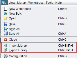
It is possible to save customised libraries on locally by “exporting” them. The libraries are saved with the extension “.sli”. Any library item can be selected (Figure 277), and the path to the folder where these items will be saved can also be specified (Figure 278).


Library items can be shared and uploaded into SEAMCAT by using the “import” button.

Once a library element is imported ( ) into a given scenario, there remains no link between the original library element and its copy in the workspace. That is, if at some later stage a library element is modified or suppressed it will not produce any change in replicas of that library element previously pasted into existing workspaces. Upon clicking on the import button, you will have to chose from a drop down list the element that you want as shown below:
A library can be created from a workspace and exported ( )to a local library folder. SEAMCAT will automatically place the new element in the right category of the library.
13.3 Edit and share library element
When opening a library item from the workspace menu, the following interface will appear (as an example, the antenna interface is shown in the figure below).

All the library elements follow the same command feature  . They are available for you to allow:
-
Creating a new antenna, click on

-
Deleting an existing antenna, select it in the list and click on

-
Duplicating an existing antenna, select it in the list and click on
 . Reference of the new antenna is derived from the reference of the selected one by incrementing the integer suffix of that reference, if any, or adding character '1' to the end of the original name.
 -
Reloading the pre-defined libraries (it will delete any entries that you may have made), click
 ;
; -
Getting on-line help by clicking on

When adding a new elements, enter the name (unique identifier), description of the elements as well as their technical parameters.


Note: Tooltips are available on the buttons to remember their meaning 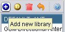
Once a broad library of various elements are populated, it might be useful to exchange it with other team members working on studies involving similar wireless systems.

The SEAMCAT library exchange files are saved using XML format with a unique file extension .sli (for Seamcat Library). Such library export file may then be distributed within a group of users and may be uploaded by any user via the command Import Library on the File menu.
In case of collision of an imported and an existing library element that have the same name (e.g, there will always be a collision between the DEFAULT library elements saved in an exchange file and those existing in target SEAMCAT copy), a choice will be given to either to overwrite the existing elements or to import new library items after renaming them.
13.4 Library elements
13.4.1 System elements
To create or modify a library element containing parameters of a particular system, i.e. generic, cellular network like CDMA or OFDMA, select the system library lements command from the Library pull-down menu or directly CTRL+SHIFT+S.
A list of existing pre-defined systems will be selectable as shown in Figure 282 for a generic system and Figure 283 for cellular systems (e.g. CDMA UL network).

When adding a new system, enter the name (unique identifier) and a description.
Note: It is also possible to create a system from the workspace and export it to a local library.
13.4.2 Spectrum emission mask elements
To create or modify a library element containing parameters of a particular spectrum mask, select the Spectrum emission masks command from the Library pull-down menu or directly with CTRL+SHIFT+S.
A list of existing pre-defined spectrum emission mask will be selectable as shown in the figure below. This is an example of a LTE UE (Table 6.6.3.1-2 of 3GPP TS 36.101) where the limit for the spurious emission domain (outside ± 12.5 MHz) applies to frequencies above 1000 MHz:

When adding a new spectrum emission mask, enter the name (unique identifier) and description of its technical parameters.
Note 1: It is possible to quickly scroll up and down and see the differences in the masks.
Note 2: It is possible to create a mask from the workspace and export it to your library environment

13.4.3 Receiver blocking mask elements
To create or modify a library element containing parameters of a particular blocking mask, select the Receiver blocking masks command from the Library pull-down menu or directly with CTRL+SHIFT+B.
A list of existing pre-defined receiver blocking mask will be selectable as shown in the figure below:

When adding a new receiver blocking mask, you need to enter the name (unique identifier) and description of its technical parameters .
Note 1: It is possible to quickly scroll up and down and see the differences in the blocking masks.
Note 2: It is possible to create a blocking mask from the workspace and export it to your library environment.
13.4.4 Receiver elements
To create or modify a library receiver element, select the Receivers command from the Library pull-down menu or directly with CTRL+SHIFT+R.
This activates the Receiver Library window which displays a list of existing receiver elements in the library. Please note that it is the same interface as in the workspace, so that it is easy to fill. If no receiver has been previously created , the list will contain only the DEFAULT receiver elements:

The parameters of receiver are grouped in 5 different panels:
-
Receiver identification: to define receiver name (unique identifier), description;
-
Antenna pointing: It contains all information relative to the antenna other than the radiation pattern (Please read here more about antenna azimuth/elevation settings);
-
Antenna patterns identification: to define a specific antenna to be associated with that particular receiver. Note that is possible to select one of the existing antenna library elements or define completely new antenna parameters to be associated only with the given receiver;
-
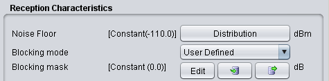
Reception characteristics: to define the basic receiver features, such as bandwidth, sensitivity, blocking (selectivity) function, etc.;
-
Interference criterion: to define the required minimum C/I and/or other interference criterion, as appropriate.
Note 1: It is possible to scroll up and down and see the differences in the receivers.
Note 2: It is possible to create a receiver from the workspace and export it to your library environment

13.4.5 Transmitter elements
To create or modify a library transmitter element, select the Transmitters command from the Library pull-down menuor directly with CTRL+SHIFT+T.
This activates the Transmitter Library window which displays a list of existing transmitter elements in the library. Please note that it is the same interface as in the workspace so that it is easy to fill. If you no transmitter has been previously created the list will contain only the DEFAULT transmitter elements:

The parameters of transmitter are grouped in 4 different panels:
-
Transmitter identification: to define name (unique identifier), description;
-
Antenna pointing: It contains all information relative to the antenna other than the radiation pattern;
-
Antenna patterns identification: to define a specific antenna to be associated with that particular receiver. Note that you can select one of the existing antenna library elements or define completely new antenna parameters to be associated only with the given receiver;
-
Emission characteristics: to define the basic transmission features, such as power, spectrum emission mask function, etc..
Note 1: It is possible to quickly scroll up and down and see the differences in the transmitters.
Note 2: It is possible to create a transmitter from the workspace and export it to your library environment
 Figure 291: Example on how to import/export to/from the workspace/library for the transmitter elements
13.4.6 CDMA Link level data
To create or modify CDMA Link level data set, select the CDMA Link level data command from the Library pull-down menu or directly CTRL+SHIFT+L. This activates the CDMA Link level data window which displays a list of existing CDMA Link level data:

Regarding the library sets of CDMA Link level data, the default sets distributed within SEAMCAT library are understood to be sufficient to cover typical CDMA systems expected to be deployed in Europe and their respective frequency bands. Any additional link level data may be defined to cover other types of CDMA systems. However, it is recommended that only users with advanced knowledge of CDMA systems develop the new CDMA Link level data for SEAMCAT simulations as several considerations should be kept in mind before creating new Link level data:
-
-
The SEAMCAT CDMA Link level data have different formats for uplink and downlink sections of CDMA link. In particular, the Link level data for uplink provides Eb / No requirements, whereas downlink data define the Ec / Ior requirements;
-
Check carefully that the newly created CDMA link level data is appropriate for the SEAMCAT's CDMA simulation methodology for the respective section of the link (uplink/downlink).
-
From the worskpace, select the relevant library item as shown below:

When adding or editing a data set, a table with data points is displayed and new data points entered will appear on the graph (for Downlink sets). For Downlink sets, every data point must as a minimum contain a geometry value, otherwise it is invalid and it will not be possible to leave the editing dialog.
Basic information about the link-level data set can be viewed and amended in by clicking Basics button in the sidebar of the edit window. This will display a new dialog.
Note: When Ok is clicked in the basics dialog any information changed in this dialog will be saved immediately even if Cancel is subsequently pressed in the overlying data point window.

13.5 Plugins Library
13.5.1 Antenna plugin elements
To create or modify a library element containing parameters of a particular antenna, select the Antennas command from the Library pull-down menu or directly with CTRL+SHIFT+A.
Since the antenna is implemented as a plugin, it is possible to include a new antenna plugin using the .jar installer and to add it to the list of existing pre-defined antennas. Any of the antenna elements is then selectable as shown in the picture below:

When adding a new antenna, enter the name (unique identifier) and description of the antenna as well as its technical parameters - peak gain and one or more radiation patterns, as necessary. See Annex A11.6 for further details.
Note 1: It is possible to quickly see the antenna pattern with mouse-over capability on top of the pattern button.
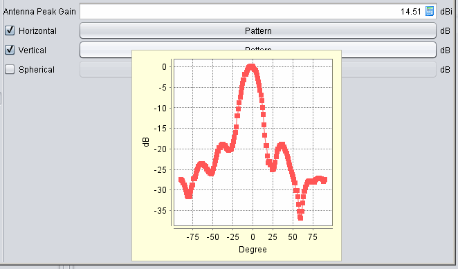
Note 2: If none of the radiation patterns is checked, SEAMCAT will assume this being an omni-directional antenna.
Note 3: It is possible to create an antenna from the workspace and export it to your library environment.
13.5.2 Coverage radius plugin elements
To create or modify a coverage radius element, select the Coverage radius library command from the Library pull-down menu or directly CTRL+SHIFT+C. This activates the Coverage radius library window which displays a list of existing Coverage radius options:

13.5.3 Propagation model plugin
To create or modify a library element containing parameters of a particular propagation model, select the Propagation model command from the Library pull-down menu or directly with CTRL+SHIFT+P.
Since the propagation models are implemented as plugin, it is possible to include a new propagation model using the .jar installer and to add it to the list of existing pre-defined models. Any of the propagation models is then selectable as shown in the picture below:

More detailed information on specific propagation models is available in ANNEX 17:
13.5.4 Event Processing Plugin
To create or modify a library element containing parameters of a particular event processing plugin, select the event processing plugin command from the Library pull-down menu or directly with CTRL+SHIFT+E. A list of available built-in event processing plugin is available in Figure 240.