13.4 Library elements
- 13.4.1 System elements
- 13.4.2 Spectrum emission mask elements
- 13.4.3 Receiver blocking mask elements
- 13.4.4 Receiver elements
- 13.4.5 Transmitter elements
- 13.4.6 CDMA Link level data
13.4.1 System elements
To create or modify a library element containing parameters of a particular system, i.e. generic, cellular network like CDMA or OFDMA, select the system library lements command from the Library pull-down menu or directly CTRL+SHIFT+S.
A list of existing pre-defined systems will be selectable as shown in Figure 282 for a generic system and Figure 283 for cellular systems (e.g. CDMA UL network).

When adding a new system, enter the name (unique identifier) and a description.
Note: It is also possible to create a system from the workspace and export it to a local library.
13.4.2 Spectrum emission mask elements
To create or modify a library element containing parameters of a particular spectrum mask, select the Spectrum emission masks command from the Library pull-down menu or directly with CTRL+SHIFT+S.
A list of existing pre-defined spectrum emission mask will be selectable as shown in the figure below. This is an example of a LTE UE (Table 6.6.3.1-2 of 3GPP TS 36.101) where the limit for the spurious emission domain (outside ± 12.5 MHz) applies to frequencies above 1000 MHz:

When adding a new spectrum emission mask, enter the name (unique identifier) and description of its technical parameters.
Note 1: It is possible to quickly scroll up and down and see the differences in the masks.
Note 2: It is possible to create a mask from the workspace and export it to your library environment

13.4.3 Receiver blocking mask elements
To create or modify a library element containing parameters of a particular blocking mask, select the Receiver blocking masks command from the Library pull-down menu or directly with CTRL+SHIFT+B.
A list of existing pre-defined receiver blocking mask will be selectable as shown in the figure below:

When adding a new receiver blocking mask, you need to enter the name (unique identifier) and description of its technical parameters .
Note 1: It is possible to quickly scroll up and down and see the differences in the blocking masks.
Note 2: It is possible to create a blocking mask from the workspace and export it to your library environment.
13.4.4 Receiver elements
To create or modify a library receiver element, select the Receivers command from the Library pull-down menu or directly with CTRL+SHIFT+R.
This activates the Receiver Library window which displays a list of existing receiver elements in the library. Please note that it is the same interface as in the workspace, so that it is easy to fill. If no receiver has been previously created , the list will contain only the DEFAULT receiver elements:

The parameters of receiver are grouped in 5 different panels:
-
Receiver identification: to define receiver name (unique identifier), description;
-
Antenna pointing: It contains all information relative to the antenna other than the radiation pattern (Please read here more about antenna azimuth/elevation settings);
-
Antenna patterns identification: to define a specific antenna to be associated with that particular receiver. Note that is possible to select one of the existing antenna library elements or define completely new antenna parameters to be associated only with the given receiver;
-
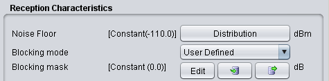
Reception characteristics: to define the basic receiver features, such as bandwidth, sensitivity, blocking (selectivity) function, etc.;
-
Interference criterion: to define the required minimum C/I and/or other interference criterion, as appropriate.
Note 1: It is possible to scroll up and down and see the differences in the receivers.
Note 2: It is possible to create a receiver from the workspace and export it to your library environment

13.4.5 Transmitter elements
To create or modify a library transmitter element, select the Transmitters command from the Library pull-down menuor directly with CTRL+SHIFT+T.
This activates the Transmitter Library window which displays a list of existing transmitter elements in the library. Please note that it is the same interface as in the workspace so that it is easy to fill. If you no transmitter has been previously created the list will contain only the DEFAULT transmitter elements:

The parameters of transmitter are grouped in 4 different panels:
-
Transmitter identification: to define name (unique identifier), description;
-
Antenna pointing: It contains all information relative to the antenna other than the radiation pattern;
-
Antenna patterns identification: to define a specific antenna to be associated with that particular receiver. Note that you can select one of the existing antenna library elements or define completely new antenna parameters to be associated only with the given receiver;
-
Emission characteristics: to define the basic transmission features, such as power, spectrum emission mask function, etc..
Note 1: It is possible to quickly scroll up and down and see the differences in the transmitters.
Note 2: It is possible to create a transmitter from the workspace and export it to your library environment
 Figure 291: Example on how to import/export to/from the workspace/library for the transmitter elements
13.4.6 CDMA Link level data
To create or modify CDMA Link level data set, select the CDMA Link level data command from the Library pull-down menu or directly CTRL+SHIFT+L. This activates the CDMA Link level data window which displays a list of existing CDMA Link level data:

Regarding the library sets of CDMA Link level data, the default sets distributed within SEAMCAT library are understood to be sufficient to cover typical CDMA systems expected to be deployed in Europe and their respective frequency bands. Any additional link level data may be defined to cover other types of CDMA systems. However, it is recommended that only users with advanced knowledge of CDMA systems develop the new CDMA Link level data for SEAMCAT simulations as several considerations should be kept in mind before creating new Link level data:
-
-
The SEAMCAT CDMA Link level data have different formats for uplink and downlink sections of CDMA link. In particular, the Link level data for uplink provides Eb / No requirements, whereas downlink data define the Ec / Ior requirements;
-
Check carefully that the newly created CDMA link level data is appropriate for the SEAMCAT's CDMA simulation methodology for the respective section of the link (uplink/downlink).
-
From the worskpace, select the relevant library item as shown below:

When adding or editing a data set, a table with data points is displayed and new data points entered will appear on the graph (for Downlink sets). For Downlink sets, every data point must as a minimum contain a geometry value, otherwise it is invalid and it will not be possible to leave the editing dialog.
Basic information about the link-level data set can be viewed and amended in by clicking Basics button in the sidebar of the edit window. This will display a new dialog.
Note: When Ok is clicked in the basics dialog any information changed in this dialog will be saved immediately even if Cancel is subsequently pressed in the overlying data point window.
