introduction
The ILT to VLR path can have several combinations as shown in Figure 224. Four panels characterised the path between the ILT and ILR.

Figure 221: ILT to VLR path combination with generic and cellular system
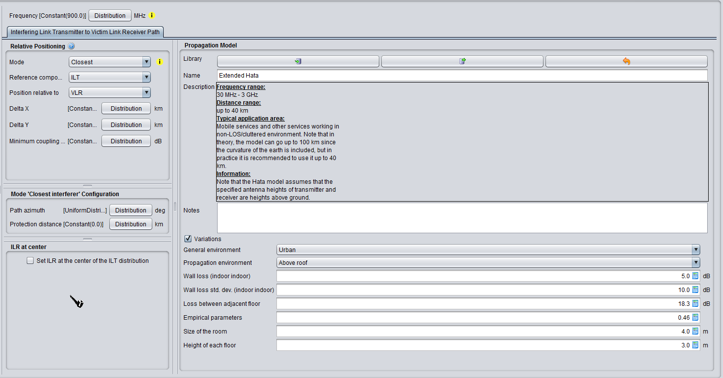
Figure 222: Transmitter to Victim Link Receiver Path (ILT -> VLR)