10.4.1 Spectrum sensing characteristics
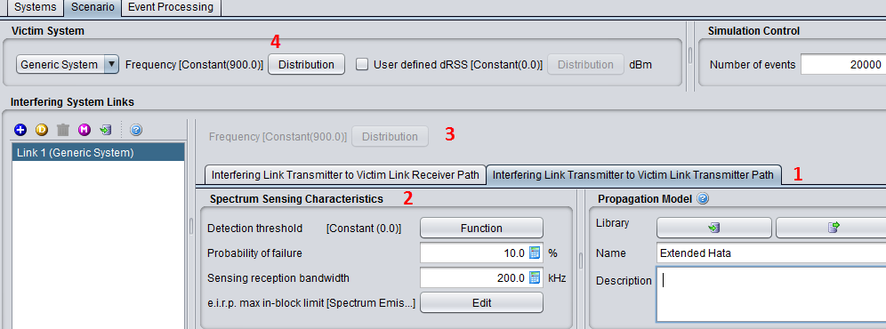
When the spectrum sensing is activated, the tab “Interfering link transmitter to victim link transmitter path” will become editable (#1 of Figure 231) and you can set the input parameters of the CR algorithm (#2). Note that the frequency of the interferer is disabled (#3). The purpose of the CR algorithm in SEAMCAT automatically calculates the number of possible channels the WSD will operate in based on the operating frequency range of the victim system and its victim link receiver bandwidth (#4).
You can not simulate “OFDMA/CDMA” as a victim and have a CR interferer. The implementation only considers generic versus generic
When an interferer is set as a CR, the emission characteristics (i.e. transmitted power, emission mask and unwanted emission mask) have to be entered (see Section 6.3) and the spectrum sensing characteristics presented in Figure 232 have to be entered.
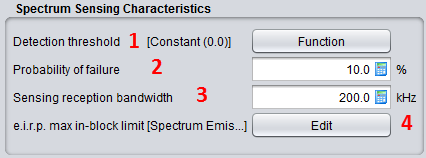
Table 48: Spectrum sensing characteristics
|
Description |
Symbol |
Type |
Unit |
Comments |
|
Detection threshold: |
|
Function (X,Y) or Scalar (offset) |
dBm |
Define the detection threshold for the spectrum sensing in a offset function. |
|
Probability of failure: |
|
Scalar |
% |
You can select this function as shown in #2 of Figure 232. The probability of failure is given in percentage. In the illustration below a probability of failure of 10% is entered. |
|
Sensing reception bandwidth |
|
Scalar |
kHz |
Define the bandwidth of the sensing device (i.e. ILT). It is used in the calculation of the sRSS: This is a constant value given in kHz as shown in #3 of Figure 232. |
|
e.i.r.p. max In-block limit |
|
Function (X,Y) (offset) |
Offset (MHz)/ Mask (dBm)/ Ref.BW (kHz) |
Define the E.I.R.Pmax In-block limit to protect the victim system as an offset function where the offset 0 is refered to the selected interfering frequency. The outcome of the algorithm set the allowed power at the ILT. |