10.4 Interfering link transmitter to victim link transmitter path (spectrum sensing)
- 10.4.1 Spectrum sensing characteristics
- 10.4.2 Detection of threshold
- 10.4.3 Probability of failure
- 10.4.4 Adjacent channel scenario - e.i.r.p. max. in-block limit
- 10.4.5 Propagation Model
10.4.1 Spectrum sensing characteristics
When the spectrum sensing is activated, the tab “Interfering link transmitter to victim link transmitter path” will become editable (#1 of Figure 231) and you can set the input parameters of the CR algorithm (#2). Note that the frequency of the interferer is disabled (#3). The purpose of the CR algorithm in SEAMCAT automatically calculates the number of possible channels the WSD will operate in based on the operating frequency range of the victim system and its victim link receiver bandwidth (#4).
You can not simulate “OFDMA/CDMA” as a victim and have a CR interferer. The implementation only considers generic versus generic
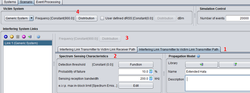
When an interferer is set as a CR, the emission characteristics (i.e. transmitted power, emission mask and unwanted emission mask) have to be entered (see Section 6.3) and the spectrum sensing characteristics presented in Figure 232 have to be entered.
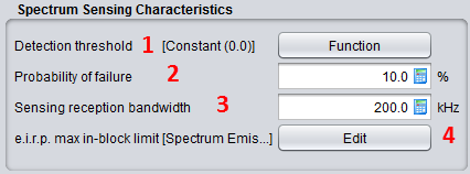
Table 48: Spectrum sensing characteristics
|
Description |
Symbol |
Type |
Unit |
Comments |
|
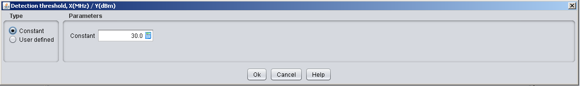
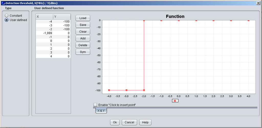
Detection threshold: |
|
Function (X,Y) or Scalar (offset) |
dBm |
Define the detection threshold for the spectrum sensing in a offset function. |
|
Probability of failure: |
|
Scalar |
% |
You can select this function as shown in #2 of Figure 232. The probability of failure is given in percentage. In the illustration below a probability of failure of 10% is entered. |
|
Sensing reception bandwidth |
|
Scalar |
kHz |
Define the bandwidth of the sensing device (i.e. ILT). It is used in the calculation of the sRSS: This is a constant value given in kHz as shown in #3 of Figure 232. |
|
e.i.r.p. max In-block limit |
|
Function (X,Y) (offset) |
Offset (MHz)/ Mask (dBm)/ Ref.BW (kHz) |
Define the E.I.R.Pmax In-block limit to protect the victim system as an offset function where the offset 0 is refered to the selected interfering frequency. The outcome of the algorithm set the allowed power at the ILT. |
10.4.2 Detection of threshold
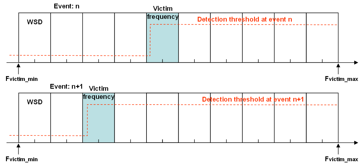
In relation to the spectrum sensing results, if this CR detect that a victim system is in the vicinity it will select an appropriate operating frequency and it will lower its emission based on an e.i.r.p. max in block limit defined in the spectrum sensing characteristics. Figure 233 presents an example of the detection threshold (a) as a constant or (b) as a function and illustrates in (c) where the offset refers to and its evolution from event to event.
|
|
|---|
|
(a) |
|
|
|
(b) |
|
|
|
(c) |
|
Figure 233: Example of the detection threshold (a) as a constant or (b) as a function and illustrates in (c) where the offset refers to |
10.4.3 Probability of failure
This feature is input selectable (by default, it is de-activated).The probability of failure may account for the failure in selecting wrongly a non_available channel for one event.
This means that when a failure appears, a channel which was initially selected as occupied by a victim DTT becomes “wrongly” available for the WSD to transmit. This results in a “conflict” situation.
For instance with a defined pfailure , that means that for x total of WSD (initial input to SEAMCAT) there is x*pfailure WSDs which will transmit in the victim frequency without power constraint. pfailure is an input parameter.
10.4.4 Adjacent channel scenario - e.i.r.p. max. in-block limit
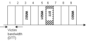
In the case where the WSDs are not allowed to transmit in the same operating frequency as for the victim DTT device, the WSDs can decide to transmit in the adjacent bands or channels. This scenario is illustrated in Figure 234 In this example the WSDs have sensed that in the channel 6 there is a victim system (here a DTT), therefore the WSDs will choose other channels to transmit.
The maximum permitted in-block and out-of-block e.i.r.p. of autonomous CRs would be specified as a function of the guard band with respect to DTT channels used in the local proximity of the CR. The available guard band would be identified by comparison of the detected DTT signal powers against a fixed detection threshold.
The purpose of the SEAMCAT simulation is to investigate the level of interference created by WSDs to the DTT victim device. Therefore the iRSSunwanted and iRSSblocking for a WSD will be computed.
As a reminder, the e.i.r.p. (Equivalent isotropically radiated power) is defined as:
 (Eq. 66)
where Lc is the cable loss in dB. We will neglect Lc.
Extract the Tx power = e.i.r.p. max - GmaxIt→VLR and calculate the iRSSunwanted and the iRSSblocking from the WSD to the victim DTT device. As a result, the interference calculation can be performed on the summation of the iRSSunwanted per channel and iRSSblocking per channel in the case where there are multiple active WSDs per channel. The determination of the e.i.r.p. max in-block limit is illustrated in Annex A16.2.
An example of In-block input values (dBm), is presented in Table 49 and Figure 235 illustrates how to set this parameter in SEAMCAT.
Table 49: Example of In-block CR e.i.r.p. max. emission limits as a function of guard band with respect to a victim DTT with channel bandwidth of 8 MHz (source SE43(10)18)
|
DTT in use at |
In-block CR e.i.r.p. max limit (dBm) |
|
co-channel |
-¥¥ |
|
n ± 1 |
-12.8 |
|
n ± 2 |
3.2 |
|
n ± 3 |
11.2 |
|
n ± 4 |
16.2 |
|
n ± 5 |
20.2 |
|
n - 6 |
16.2 |
|
n + 6 |
21.2 |
|
n ± 7 |
22.2 |
|
n ± 8 |
23.2 |
|
n - 9 |
4.2 |
|
n + 9 |
23.2 |
|
n ± 10 |
24.2 |
|
> n ± 11 |
25.2 |
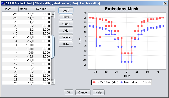
Figure 235: GUI of the In-block CR e.i.r.p. max limit (dBm)
10.4.5 Propagation Model
You can choose the suitable propagation model to be applied when calculating signal loss along the transmitter and the receiver path. A choice and settings of propagation models are presented in ANNEX 17:.