# 1.4 Interference calculations in generic systems

# 1.4.1 Introduction

In this section the interference calculations for ‘generic’ systems are described. Cellular systems (<span data-highlighted="true" data-vc="highlighted-text"><span class="_kqswh2mm"><span class="_5pioz8co _189e1dm9 _1il9buyh _19lc184f _d0altlke" data-testid="definition-highlighter">OFDMA</span></span></span> and <span data-highlighted="true" data-vc="highlighted-text"><span class="_kqswh2mm"><span class="_5pioz8co _189e1dm9 _1il9buyh _19lc184f _d0altlke" data-testid="definition-highlighter">CDMA</span></span></span>) use a different interference calculation method based on throughput and capacity loss which are described in more detail in [ANNEX 15](https://ecowiki.atlassian.net/wiki/spaces/SH/pages/494646/A15+Cellular+algorithms#A15Cellularalgorithms-A15 "https://ecowiki.atlassian.net/wiki/spaces/SH/pages/494646/A15+Cellular+algorithms#A15Cellularalgorithms-A15"):

# 1.4.2 An illustration with C/I as interference criterion

The C/I ratio available at the victim receiver’s input is computed using both the iRSS (Interfering Received Signal Strength) and the dRSS (desired Received Signal Strength),. Figure 7 illustrates the various signal levels used to determine whether or not interference is occurring.

Figure 7(a) represents the situation in case of no interference - the <span data-highlighted="true" data-vc="highlighted-text"><span class="_kqswh2mm"><span class="_5pioz8co _189e1dm9 _1il9buyh _19lc184f _d0altlke" data-testid="definition-highlighter">VLR</span></span></span> is receiving the dRSS with some safe margin above its sensitivity level. The victim’s signal level is the sum of the sensitivity and wanted signal margin l.

Figure 7 (b) illustrates the case of tolerable interference. The interference power iRSS adds to the noise floor power resulting in an increase of the noise floor. The example introduces an increase of 1 dB of the noise floor caused by an iRSS 6 dB below the noise floor. As a result the wanted signal margin is also reduced by 1 dB assuming a constant wanted signal power. However since the original wanted signal margin is much larger the interference is tolerable –i.e. the C/I ratio available at the receiver’s input is larger than the S/N required for the operation of the system.

Figure 7(c) shows the case of interference which can not be tolerated – i.e. the operation of the system is impaired. The power sum of all the interfering signals including the noise floor of the receiver results in an insufficient wanted signal margin -, i.e. the C/I ratio available at the receivers input is less than the S/N ratio required for the intended operation.

[![image.png](https://wiki.cept.org/uploads/images/gallery/2026-04/scaled-1680-/92R3VBrP7kGAWJGh-image.png)](https://wiki.cept.org/uploads/images/gallery/2026-04/92R3VBrP7kGAWJGh-image.png)

**Figure 7: Levels used to determine whether or not interference is occurring**

As a receiver cannot distringuish between various sources of interference or noise, the sum of all interefing signals including the receiver noise floor has to be taken into account. The C/I ratio available at the receiver’s input must be greater than the S/N required for the operation of the system if the interference is to be avoided. SEAMCAT checks for this condition and records whether or not degradation due to interference is occurring. This is illustrated further in Figure 8

The Monte Carlo technique works by considering many independent events in time (or in space). For each instant a scenario is built up using a number of different random variables, i.e. where the interferer is located with respect to the victim, the signal strength of the wanted signal, which channels the victim and interferer are using etc. If a sufficient number of simulation trials are run then the probability of a certain event occurring can be calculated with a high level of accuracy.

In this way, the tool is able to quantify the ***probability of interference*** between radio systems and is able to help determine appropriate frequency arrangement rules or identify suitable limits for transmitter/receiver performance.

You can select the ***interfering modes*** (unwanted and blocking) as well as the ***interference criteria*** of your choice in SEAMCAT as shown in Figure 97.

![image.png](https://wiki.cept.org/uploads/images/gallery/2026-04/scaled-1680-/5XejfZnvyIQu63bO-image.png) **Figure 8: Illustrative summary of the interference criteria computation**

# 1.4.3 Methodology associated to the interference criterion (C/I, C/(I+N), (N+I)/N, I/N)

Four interference criteria are considered within SEAMCAT:

- C/I : Carrier to interference ratio;
- C/(I+N) : Carrier to interference plus noise ratio;
- (N+I)/N : Desensitisation;
- I/N : Interference to noise ratio.

All of these criteria can be specified as an input to your simulation. (Figure 9), but a single criteria needs to be chosen for the interference calculation (Figure 10). Multiple interference calculations are possible on the same set of results if more than one criterion are used separately. In the example below the criterion for interference to occur for the <span data-highlighted="true" data-vc="highlighted-text"><span class="_kqswh2mm"><span class="_5pioz8co _189e1dm9 _1il9buyh _19lc184f _d0altlke" data-testid="definition-highlighter">VLR</span></span></span> isa carrier to interference ratio (C/I) less than the minimum allowable value of 19 dB-

These parameters are also used in the evaluation of the two blocking modes (Protection ratio and Sensitivity, see section [1.4.5](https://ecowiki.atlassian.net/wiki/spaces/SH/pages/493804/1.4.5+Unwanted+emissions#id-1.4.5Unwantedemissions-1.4.5 "https://ecowiki.atlassian.net/wiki/spaces/SH/pages/493804/1.4.5+Unwanted+emissions#id-1.4.5Unwantedemissions-1.4.5")).

<table border="1" id="bkmrk-figure-9%3A-interferen" style="border-collapse: collapse; width: 100%; height: 29.6px;"><colgroup><col style="width: 50%;"></col><col style="width: 50%;"></col></colgroup><tbody><tr style="height: 29.6px;"><td style="height: 29.6px;">![image.png](https://wiki.cept.org/uploads/images/gallery/2026-04/scaled-1680-/9fPdN3va74hwC219-image.png)

</td><td style="height: 29.6px;">![image.png](https://wiki.cept.org/uploads/images/gallery/2026-04/scaled-1680-/qznPGJhYLThTUEUO-image.png)

</td></tr><tr><td>**
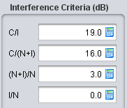
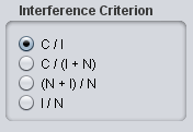
Figure 9: Interference criteria**

**values that you provide as input to your simulation**

</td><td>**Figure 10: Selection of the interference criteria**

**used for the evaluation of interference**

**(from the Interference Calculation Engine control panel)**

</td></tr></tbody></table>

# 1.4.4  Interference criteria relationship

C/I may vary typically from 9 dB (e.g. for <span data-highlighted="true" data-vc="highlighted-text"><span class="_kqswh2mm"><span class="_5pioz8co _189e1dm9 _1il9buyh _19lc184f _d0altlke" data-testid="definition-highlighter">QPSK</span></span></span>) to 26 dB or higher (e.g. for 64QAM…). By introducing artificial noise iRSS on top of the noise floor (I/N), C/I is then desensitised by (N+I)/N resulting in C/(N+I). Note that the desensitisation is exactly the factor (N+I)/N (also = 1+I/N).

Further details of the relationship are given in [ANNEX 3:](https://ecowiki.atlassian.net/wiki/spaces/SH/pages/494652/A3+Relationship+between+C+I+C+I+N+I+N+N+and+I+N#A3RelationshipbetweenC/I,C/(I+N),(I+N)/NandI/N-A "https://ecowiki.atlassian.net/wiki/spaces/SH/pages/494652/A3+Relationship+between+C+I+C+I+N+I+N+N+and+I+N#A3RelationshipbetweenC/I,C/(I+N),(I+N)/NandI/N-A").

Considering that

[![image.png](https://wiki.cept.org/uploads/images/gallery/2026-04/scaled-1680-/GTYtMv0kzr6RlavK-image.png)](https://wiki.cept.org/uploads/images/gallery/2026-04/GTYtMv0kzr6RlavK-image.png) (Eq. 12)

and assuming a C/I of 19 dB, the following examples may be considered:

- I/N = 0 dB, results in (N+I)/N = 3 dB and considering C/I = 19 dB, then C/(N+I) = C/I - 3 dB = 16 dB
- I/N = -6 dB, results in (N+I)/N » 1 dB and considering C/I = 19 dB, then C/(N+I) = C/I - 7 dB = 12 dB
- I/N = -10 dB, results in (N+I)/N » 0.4 dB and considering C/I = 19 dB, then C/(N+I) = C/I - 10 dB = 9 dB
- I/N = -20 dB, results in (N+I)/N = 0.04 » 0.1 dB and C/I = 19 dB, then C/(N+I) = C/I - 20 dB = -1 dB

 **Note:**

*In case C/(I+N) is chosen as the protection criterion:*

*if I/N ≤ -20 dB, the impact of the interferer is negligible compared to the noise floor (i.e. C/(I+N) ≈ C/N);*

*if I/N &gt; 10 dB, then C/(I+N) ≈ C/I (i.e. the interferer is more dominant than the noise).*

![image.png](https://wiki.cept.org/uploads/images/gallery/2026-04/scaled-1680-/7eWemeMzkhjkoUVd-image.png)

# 1.4.5 Unwanted emissions

The level of ***unwanted emissions*** ( i.e. consisting of the out-of-band emissions and the spurious emissions [\[8\]](https://ecowiki.atlassian.net/wiki/spaces/SH/pages/494676/A26+List+of+references#A26Listofreferences-R08 "https://ecowiki.atlassian.net/wiki/spaces/SH/pages/494676/A26+List+of+references#A26Listofreferences-R08") of the <span data-highlighted="true" data-vc="highlighted-text"><span class="_kqswh2mm"><span class="_5pioz8co _189e1dm9 _1il9buyh _19lc184f _d0altlke" data-testid="definition-highlighter">ILT</span></span></span>) falling within the <span data-highlighted="true" data-vc="highlighted-text"><span class="_kqswh2mm"><span class="_5pioz8co _189e1dm9 _1il9buyh _19lc184f _d0altlke" data-testid="definition-highlighter">VLR</span></span></span> receiver bandwidth (Figure 11) is determined using the interferer’s transmit mask, the receiver bandwidth of the <span data-highlighted="true" data-vc="highlighted-text">VLR</span>, the interferer-to-victim frequency separation, the gains of the antennas and the propagation loss. The receiver experiences the unwanted power directly as additional noise in terms of I+N. There is no possibility in terms of filtering with which the receiver could reduce this impact by itself.

Note that the receiver bandwidth is taken into account in the unwanted calculation.

Further details on the unwanted emission mask are provided in[ ANNEX 6](https://ecowiki.atlassian.net/wiki/spaces/SH/pages/494667/A6+sRSS+calculation#A6sRSScalculation-A6 "https://ecowiki.atlassian.net/wiki/spaces/SH/pages/494667/A6+sRSS+calculation#A6sRSScalculation-A6"):. Details on the iRSS<sub data-renderer-mark="true">unwanted</sub> calculation are given in [ANNEX 5](https://ecowiki.atlassian.net/wiki/spaces/SH/pages/494649/A5+iRSS+calculation#A5iRSScalculation-A5 "https://ecowiki.atlassian.net/wiki/spaces/SH/pages/494649/A5+iRSS+calculation#A5iRSScalculation-A5"):. The unwanted emission is also sometimes quantified using the term Adjacent Channel Leakage Ratio (ACLR) (see Annex [A15.7](https://ecowiki.atlassian.net/wiki/spaces/SH/pages/491958/A15.7+ACS+ACLR+AND+ACIR+APPROACH+IN+SEAMCAT#A15.7ACS,ACLRANDACIRAPPROACHINSEAMCAT-A15.7 "https://ecowiki.atlassian.net/wiki/spaces/SH/pages/491958/A15.7+ACS+ACLR+AND+ACIR+APPROACH+IN+SEAMCAT#A15.7ACS,ACLRANDACIRAPPROACHINSEAMCAT-A15.7")).

[![image.png](https://wiki.cept.org/uploads/images/gallery/2026-04/scaled-1680-/R0RQDNpy0w73iU8h-image.png)](https://wiki.cept.org/uploads/images/gallery/2026-04/R0RQDNpy0w73iU8h-image.png)

**Figure 11: Illustration of the interference due to the unwanted emissions (i.e. the unwanted emissions of <span data-highlighted="true" data-vc="highlighted-text">ILT</span> falling in the receiver bandwidth of <span data-highlighted="true" data-vc="highlighted-text">VLR</span>)**

# 1.4.6 Receiver blocking

The level of interference determined by the interferer’s transmit power, the antenna gains and propagation loss, is further decreased due to the receiver blocking performance for a given interferer/victim frequency separation. Details on the iRSS<sub data-renderer-mark="true">blocking</sub> calculation are given in [ANNEX 5](https://ecowiki.atlassian.net/wiki/spaces/SH/pages/494649 "https://ecowiki.atlassian.net/wiki/spaces/SH/pages/494649"):.

Note that from SEAMCAT 5.0.1 onwards, the blocking attenuation is computed at the <span data-highlighted="true" data-vc="highlighted-text"><span class="_kqswh2mm"><span class="_5pioz8co _189e1dm9 _1il9buyh _19lc184f _d0altlke" data-testid="definition-highlighter">ILT</span></span></span> frequency and that the <span data-highlighted="true" data-vc="highlighted-text">ILT</span> bandwidth is nowconsidered (see [ANNEX 8](https://ecowiki.atlassian.net/wiki/spaces/SH/pages/494660/A8+Receiver+selectivity+and+blocking+attenuation#A8Receiverselectivityandblockingattenuation-A8 "https://ecowiki.atlassian.net/wiki/spaces/SH/pages/494660/A8+Receiver+selectivity+and+blocking+attenuation#A8Receiverselectivityandblockingattenuation-A8"):). There are 3 ways to calculate the blocking response which are described in more detail in [ANNEX 8](https://ecowiki.atlassian.net/wiki/spaces/SH/pages/494660/A8+Receiver+selectivity+and+blocking+attenuation#A8Receiverselectivityandblockingattenuation-A8 "https://ecowiki.atlassian.net/wiki/spaces/SH/pages/494660/A8+Receiver+selectivity+and+blocking+attenuation#A8Receiverselectivityandblockingattenuation-A8")::

*User Defined (dB): Att<sub data-renderer-mark="true">Blocking</sub> = Block<sub data-renderer-mark="true">UD (dB) </sub>(Eq. 13)*

*Protection Ratio (dB): Att<sub data-renderer-mark="true">Blocking</sub> = Block<sub data-renderer-mark="true">PR</sub> <sub data-renderer-mark="true">(dB)</sub> + C/(N+I) <sub data-renderer-mark="true">(dB)</sub> + (N+I)/N <sub data-renderer-mark="true">(dB)</sub> - I/N <sub data-renderer-mark="true">(dB) </sub>(Eq. 14)*

*Sensitivity Mode (dBm): Att<sub data-renderer-mark="true">Blocking</sub> = Block<sub data-renderer-mark="true">Sens</sub> <sub data-renderer-mark="true">(dBm)</sub> – Sensitivity<sub data-renderer-mark="true"><span data-highlighted="true" data-vc="highlighted-text"><span class="_kqswh2mm"><span class="_5pioz8co _189e1dm9 _1il9buyh _19lc184f _d0altlke" data-testid="definition-highlighter">VLR</span></span></span></sub> <sub data-renderer-mark="true">(dBm)</sub> + C/(N+I) <sub data-renderer-mark="true">(dB)</sub> – I/N <sub data-renderer-mark="true">(dB) </sub>(Eq. 15)*

[![image.png](https://wiki.cept.org/uploads/images/gallery/2026-04/scaled-1680-/W7MjEAtc17C357hZ-image.png)](https://wiki.cept.org/uploads/images/gallery/2026-04/W7MjEAtc17C357hZ-image.png)**Figure 12: Illustration of the blocking of the victim link receiver (i.e. total emission power of <span data-highlighted="true" data-vc="highlighted-text">ILT</span> reduced by the blocking attenuation (selectivity) function of the <span data-highlighted="true" data-vc="highlighted-text">VLR</span>**

# 1.4.7 Intermodulation

The ***intermodulation interference***, i.e. the power of intermodulation products, reduced by the intermodulation attenuation function of the <span data-highlighted="true" data-vc="highlighted-text"><span class="_kqswh2mm"><span class="_5pioz8co _189e1dm9 _1il9buyh _19lc184f _d0altlke" data-testid="definition-highlighter">VLR</span></span></span> can be used in interference calculations. See [ANNEX 5](https://ecowiki.atlassian.net/wiki/spaces/SH/pages/494649/A5+iRSS+calculation#A5iRSScalculation-A5 "https://ecowiki.atlassian.net/wiki/spaces/SH/pages/494649/A5+iRSS+calculation#A5iRSScalculation-A5"): for further details.

# 1.4.8 Overloading

Overloading threshold is the minimum interfering signal levelat which the receiver loses its ability to discriminate against interfering signals at frequencies other than that of the wanted signal. See Annex [A2.2](https://ecowiki.atlassian.net/wiki/spaces/SH/pages/492456/A2.2+OVERLOADING+CASE#A2.2OVERLOADINGCASE-A2.2 "https://ecowiki.atlassian.net/wiki/spaces/SH/pages/492456/A2.2+OVERLOADING+CASE#A2.2OVERLOADINGCASE-A2.2") for the use of overloading in interference calculation and Annex [A5.4](https://ecowiki.atlassian.net/wiki/spaces/SH/pages/492248/A5.4+OVERLOADING+CALCULATION#A5.4OVERLOADINGCALCULATION-A5.4 "https://ecowiki.atlassian.net/wiki/spaces/SH/pages/492248/A5.4+OVERLOADING+CALCULATION#A5.4OVERLOADINGCALCULATION-A5.4"). for the iRSS<sub data-renderer-mark="true">overloading</sub> calculation.

# 1.4.9 Combined interference mechanism

The combination of the ***unwanted emissions and*** ***receiver blocking*** can also be studied simultaneously in SEAMCAT as depicted in Figure 13. See Annex [A2.3](https://ecowiki.atlassian.net/wiki/spaces/SH/pages/492511/A2.3+INTERFERENCE+CALCULATION+COMBINATION#A2.3INTERFERENCECALCULATIONCOMBINATION-A2.3 "https://ecowiki.atlassian.net/wiki/spaces/SH/pages/492511/A2.3+INTERFERENCE+CALCULATION+COMBINATION#A2.3INTERFERENCECALCULATIONCOMBINATION-A2.3") for further details.

[![image.png](https://wiki.cept.org/uploads/images/gallery/2026-04/scaled-1680-/tCzRaFthIYsaKXIv-image.png)](https://wiki.cept.org/uploads/images/gallery/2026-04/tCzRaFthIYsaKXIv-image.png)

**Figure 13: Illustration of the combined unwanted emissions and the receiver blocking mechanism in SEAMCAT**

# 1.4.10 Interference calculation

SEAMCAT calculates the probability of interference for generic (i.e. non-cellular) victim systems. Each sample of dRSS and iRSS generated during a simulation is compared against the relevant signal-to-noise criterion (specified in the scenario, such as C/N, C/N+I etc). The probability of interference is calculated for all events where the dRSS is greater than the sensitivity of the victim link receiver (*dRSS* &gt; sens). This probability can be calculated for two different modes, as illustrated in [Figure 271](https://ecowiki.atlassian.net/wiki/spaces/SH/pages/493014/12.9.2+Interference+calculation+GUI#id-12.9.2InterferencecalculationGUI-F271 "https://ecowiki.atlassian.net/wiki/spaces/SH/pages/493014/12.9.2+Interference+calculation+GUI#id-12.9.2InterferencecalculationGUI-F271") of section [12.9.2](https://ecowiki.atlassian.net/wiki/spaces/SH/pages/493014 "https://ecowiki.atlassian.net/wiki/spaces/SH/pages/493014").

- **Compatibility**: This mode provides a single-figure estimate of the probability of interference in a given interference scenario;
- **Translation**: This mode calculates probability of interference as a function of changing one of the following parameters:

1. Transmitter power of the interefering link transmitter;
2. Blocking response level of the victim link receiver;
3. Intermodulation rejection level for the victim link receiver

[![image.png](https://wiki.cept.org/uploads/images/gallery/2026-04/scaled-1680-/bcUV21dd0kyliZeo-image.png)](https://wiki.cept.org/uploads/images/gallery/2026-04/bcUV21dd0kyliZeo-image.png)