1.2 Basic Radio Frequency Terminology
The following terminology has been developed to support the SEAMCAT simulation tool. While it is broadly in line with what is in use in ITU-R, ETSI, and CEPT, it may be expected that for other needs or documents, ETSI and CEPT/ECC will use different definitions, for example definitions more focused on specific equipment characteristics or aspects of such products.
- 1.2.1 Receiver thermal noise
- 1.2.2 Noise figure and Noise factor
- 1.2.3 Receiver noise floor
- 1.2.4 Receiver sensitivity
- 1.2.5 Wanted signal: dRSS
- 1.2.6 Interfering signal: iRSS
- 1.2.7 Bandwidth correction factor
- 1.2.8 Desensitisation
- 1.2.9 Blocking
- 1.2.10 Adjacent channel selectivity (ACS)
- 1.2.11 In-band, out-of-band, spurious, unwanted emission
- 1.2.12 Co channel
1.2.1 Receiver thermal noise
The thermal noise (in Watts) expressed in power level is defined as:
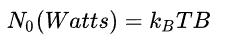
where:
-
kB is the Boltzmann's constant 1.38 x 10⁻²³ in joules per kelvin (J/K),
-
T is the receiver absolute temperature in Kelvin (K),
-
B is the bandwidth in Hertz (Hz) over which the noise is measured.
It can be seen that the noise power of eq1 is dependent on the temperature and on the bandwidth. This figure is then normally expressed in terms of dBm and is defined as:

1.2.2 Noise figure and Noise factor
Noise figure (NF) and noise factor (F) are measures of degradation of the signal-to-noise ratio (SNR), caused by components in a radio frequency (RF) signal chain. It is a number by which the performance of an amplifier or a radio receiver can be specified, with lower values indicating better performance.
The noise factor is defined as the ratio of the output noise power of a device to the portion thereof attributable to thermal noise. The noise factor is thus the ratio of actual output noise to that which would remain if the device itself did not introduce noise, or the ratio of input SNR to output SNR.
The noise figure is simply the noise factor expressed in decibels (dB).

1.2.3 Receiver noise floor
Any practical measurement will be subject to some form of noise or unwanted signal (thermal noise or interfering signals). The noise floor limits the smallest measurement that can be taken with certainty since any measured amplitude cannot on average be less than the noise floor.
The noise floor (N) is the level of noise introduced by the receiver system below which the signal that is being captured cannot be isolated from the noise, and is defined in dBm as:
N (dBm) = N0 (dBm) + NF (dB) (Eq. 4)
or in linear domain:
N (Watts) = 10^((-173.977 + 10*log10(systemBandwidth (Hz)) + NF)/10) (Eq. 5)
As an example, in SEAMCAT, for a receiver with a noise figure of 9 dB and a bandwidth of 5 MHz, the noise floor will be
-173.977 dBm/Hz +60 dB/MHz +10*log10(5 MHz) + 9 dB= -98 dBm
Another example is that for a noise figure of 4 dB and a bandwidth of 200 kHz with thermal noise = kTB = -121 dBm, the noise floor is -117 dBm.
In SEAMCAT, the input is the distribution of the strength of the noise floor. This parameter is used for the probability calculation when the criteria is C/(N+I), (I/N) or (I+N)/N.
1.2.4 Receiver sensitivity
The sensitivity of a receiver is normally taken as the minimum input signal (Smin) required to produce an output signal with a specific signal-to-noise (S/N) ratio. S/N is a required minimum ratio, if N is increased, then S must also be increased to maintain the S/N ratio. The threshold value is chosen high enough above the mean noise level so that the probability of random noise peaks exceeding the threshold, and causing false alarms, is acceptably low. It is defined (in log domain/dB) as
 (Eq. 6)
In SEAMCAT, the following equation (in log domain/dB) is applied:
 (Eq. 7)
Where C/(N+I) is the carrier (or signal) to interference plus noise ratio as input to SEAMCAT. The S/N is equal to the C/(N+I) in the absence of any interferer.
In SEAMCAT, this is used in the calculation of the receiver attenuation in Sensitivity mode. See Annex A8.5 for further details.
1.2.5 Wanted signal: dRSS
The victim’s wanted signal strength also called desired Received Signal Strength (dRSS), corresponding to the carrier level (C), is calculated as a simple link budget between the victim link receiver (VLR) and the victim link transmitter (VLT) as described in ANNEX 4:.
1.2.6 Interfering signal: iRSS
The interfering Received Signal Strength (iRSS), corresponding to the interference level (I), is calculated as a link budget between the VLR and the interfering link transmitter (ILT) as described in ANNEX 5:.
The various interference mechanisms resulting in different iRSS (i.e. unwanted, blocking and intermodulation) are described in Section 1.4.5.
1.2.7 Bandwidth correction factor
When the bandwidth of the interferer and the victim are different, SEAMCAT automatically applies a bandwidth correction factor to calculate the unwanted emission power for a specific bandwidth.
The following example introduces an interferer transmitting 2 W. This is equivalent to 33 dBm (see conversion in Table 97). The amount of energy that a VLR receives in its bandwidth can be derived according to these two cases illustrated in Figure 1.
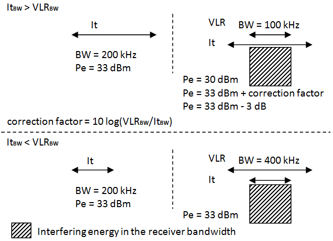
Further examples of correction bandwidth can be found in section 3.3.8.
1.2.8 Desensitisation
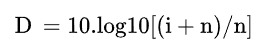
Desensitisation (D) of the receiver in the presence of an interfering signal, given in dB, corresponds to the ‘noise rise’ or ‘noise augmentation’ due to the interfering signal and is derived by the following equation in dB:
 (Eq. 8)
and is equivalent in the linear domain to:
 (Eq. 9)
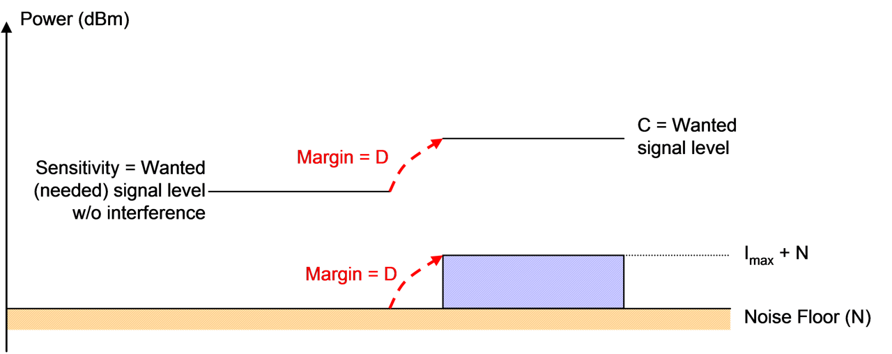
To ensure proper operation, the receiver is designed to include a margin equal or lower than D which allows it to tolerate a certain level of interference (I) in the listened channel. This can be caused by co-channel and/or non-co-channel interference sources.
When running a radio network or a radio link, the objective is to maintain the signal to interference and noise ratio SINR equal to the sensitivity to noise ratio. This is illustrated in the following figure.
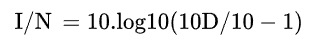
An equivalent expression of the desensitisation, (N+I)/N, is expressed as follows in terms of interference to noise ratio I/N in dB.
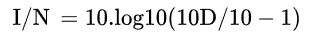 (Eq. 10)
noting that in linear domain it is equivalent to:
 (Eq. 11)
1.2.9 Blocking
The term “Blocking” is used in SEAMCAT to describe the capability of the victim receiver to receive a wanted modulated signal without exceeding a given degradation due to the presence of an unwanted input signal on a different frequency than the one of the wanted signal.
It has to be noted that most standards and specifications distinguish between the receiver selectivity given as Adjacent Channel Selectivity (ACS) for frequency offsets close to the centre frequency of the VLR, and Blocking (a term often associated with desensitisation) for frequency offsets far away from the centre frequency of the VLR. It is assumed that the receiver blocking performance is flat over the bandwidth of the interfering signal.
1.2.10 Adjacent channel selectivity (ACS)
The receiver selectivity is often given as Adjacent Channel Selectivity (ACS) – i.e. when the concept of "channel" has been defined for the system being considered. As the wording suggests, this parameter defines the requirement in case one single ILT is set at the centre frequency of the (first) adjacent channel. The values for the second and third adjacent channel are occasionally also defined by a standard. However, standards generally implicitly define the interfering signal as of the same system type as the victim, i.e. using the same bandwidth and generally the same or at least a similar modulation scheme.
1.2.11 In-band, out-of-band, spurious, unwanted emission
In-band emission is understood as relating to the necessary bandwidth.
The ITU-R Radio Regulations define the followings in Nos. 1.152, 1.144, 1.145 and 1.146:
1.152 Necessary bandwidth: For a given class of emission, the width of the frequency band which is just sufficient to ensure the transmission of information at the rate and with the quality required under specified conditions.
1.144 Out-of-band emission: Emission on a frequency or frequencies immediately outside the necessary bandwidth which results from the modulation process, but excluding spurious emissions.
1.145 Spurious emission: Emission on a frequency or frequencies which are outside the necessary bandwidth and the level of which may be reduced without affecting the corresponding transmission of information. Spurious emissions include harmonic emissions, parasitic emissions, intermodulation products and frequency conversion products, but exclude out-of-band emissions.
1.146 Unwanted emissions: Consist of spurious emissions and out-of-band emissions
These definitions are illustrated in the following figure (see also Figure 1 in ECC Recommendation (02)05 [18]):
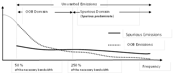 Figure 3: Illustration of the OOB and Spurious Domains
1.2.12 Co channel
A co-channel interference scenario can be illustrated as shown in figure below. In this case a part or the whole component of the interference is within the receiver bandwidth of the victim receiver.

Figure 4: Co-channel interference scenario